I’ve always thought of those clap-activated switches as a bit of a gimmick—after all, you can always just move the lightswitch if it’s that hard to get at. But currently my mother is hobbling around on crutches, and it suddenly struck me that turning the uplighter on from the doorway would be handy. A rummage through the junkbox found a board—I think from an old washing machine—full of relays, and 5v relays at that, so no need for a voltage multiplier to turn the relay on. I also found an old ‘usb charger’ rated at 1A 4.2V (?!), which is thankfully enough to turn on the relay.
Looking over the internet, most people just feed a common-emitter npn with an appropriately biased mic; some use a darlington for more gain. I could just feed this into a 555 bistable and rely on amplitude alone to prevent false triggering, but that seems a little crude; also, the room is used for music lessons, and clapping is not unheard of. It would be better to have some distinctive pattern; after a little thought I came up with the following:
The microphone (an electret pulled from something once) is biased by the 1k and parallel 10k resistors: ideal biasing was somewhere between 1k and 5k, and I had no 5K pot. The 10k is logarithmic anyhow, so the adjustment curve is fun. The first two transistors amplify in common-emmitter mode, the second being an easy point to add amplification by biasing the base up with a resistor if needed.
This feeds two 555 timers, both in monostable mode. The first (top) generates a 110ms pulse to debounce the input; the second (bottom) generates a pulse between .1 and ~3s for the timeout circuit. Continuing to the right on the top, two flip-flops form a kind of ring counter: the rightmost toggles, driving the relay, after the leftmost has recieved two rising edges (i.e. two claps). The reset circuit is crude: the leftmost flip-flop is reset and the rightmost is set to its current state (i.e. unaffected—and any momentary glitch ought to be held on by relay which takes a while to turn off anyhow). To ensure that the leftmost doesn’t toggle the rightmost when it resets I added a 10nf capacitor on the base of the transistor (which takes a moment to charge, thus adding a slight delay—or you can say it’s a low-pass filter and curves the sharp rising edge). These are both fed from the lower 555, inverted, via a 22uF capacitor to generate a short-ish pulse (about 10ms)—the inversion being so that the pulse comes at the end of the reset window.
Not shown are most of the decoupling capacitors, which turned out to be essential to stop the flip-flops going mad, the protection diode across the relay coil (otherwise it never turns off!); the hefty (22uF) electrolytic near the transistors (top left) stops them putting enough load on the supply to cause a loud clap to register as two, or even more: this puzzled me for a while until I thought of it.
Most useful of all is the LED on Q of the first flip-flop, which turns on during the low window (F1 in the timing diagram). Without this, use is highly frustrating. With the LED you adjust the threshold pot until it turns on when you clap (taking care to give it some margin—the supply drifts, and as the relay makes some noise turning off it can go into oscillation, which is not good), and then adjust the ‘window’ pot, watching the LED. It will turn off by itself under the reset timeout, and the game is to set a long enough timeout to be able to turn the LED off—and the output on—first. Here’s the two pots:
I should probably put knobs on them. But this is not for long term usage (after all, it’s drawing current to turn on). Here’s the breadboard, a bit of the insulating hardboard added:
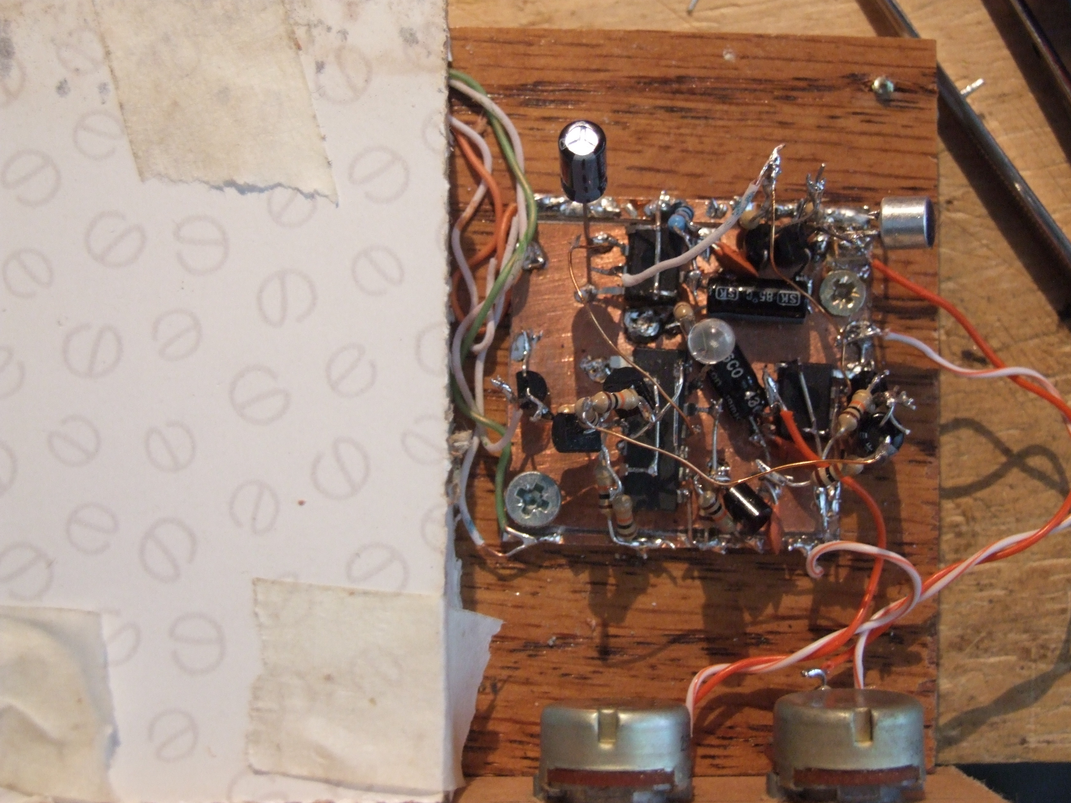
A closeup of the board (rather cramped) and the mains enclosure, safe if not pretty:
And it works! Not bad for an evening’s inspiration. At some point I might even add a video or something to prove it. And if anyone else does this—unless like me you have a lot of random parts around, save yourself the hassle and use a microprocessor, or maybe even dsp on a computer.