Dad rather liked my clock. In fact, he went looking for ‘a clock with hands and an adjustable chime’. Which, of course, made me wonder whether I could make one.
The first question was the hands: I liked the leds at the front of mine, and didn’t see the point in moving real hands around with a stepper motor or something of the kind. A digital clock should, I think, look digital. Looking online for things like ’led ring clocks’ showed the odd design, but none with all three hands in one ring, and three rings struck me as a bit much. Thus I started looking on farnell for bicolour leds to make the hands out of, and found an orange/red led on clearance at around 10p each: and also some red/green rectangular leds. Now, wouldn’t it be nice to have the ’ticks’ in the display differently shaped as well as coloured?
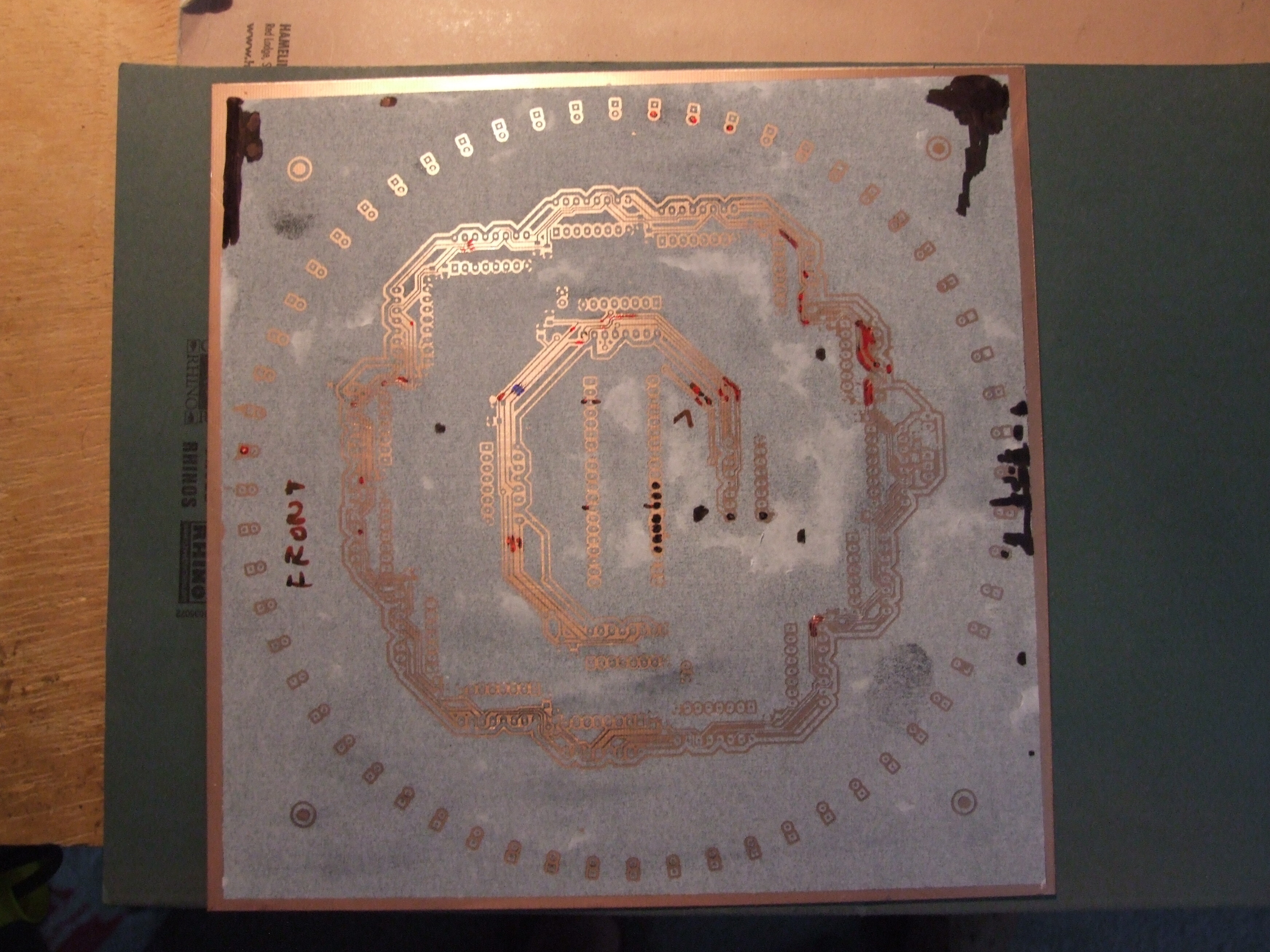
But how to drive it all? I’d assumed the same underlying hardware as mine, but a multiplexed display was clearly out of the question. At this point I got everything wrong: rather than googling ‘serial led driver ic’ I set about designing my own: a set of cascaded shift registers, with the leds connected between outputs so that ‘10’ would give red and ‘01’ green (‘11’ is forbidden in software). I’d never built anything of the kind and assumed that one just wired the clocks together and the outputs to inputs; after testing on a breadboard with two ics a board was designed accordingly, aiming at being as aesthetically pleasing as possible:
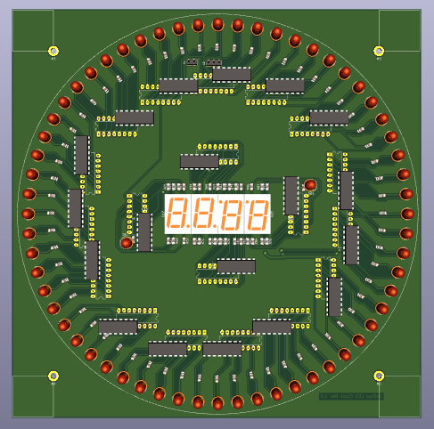
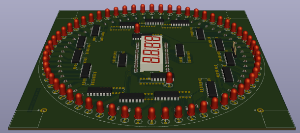
This board is riddled with mistakes: the clock and latch are actually wired in rings (!), the clocks are fed in the same order as the data (and thus lag), the tolerences are rather fine, and multiple tracks are fed between ics to avoid vias. I’d never made a double-sided board before, but toner transfer worked really well for smaller boards, so why not?
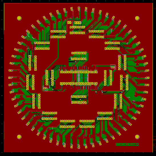
Main Board
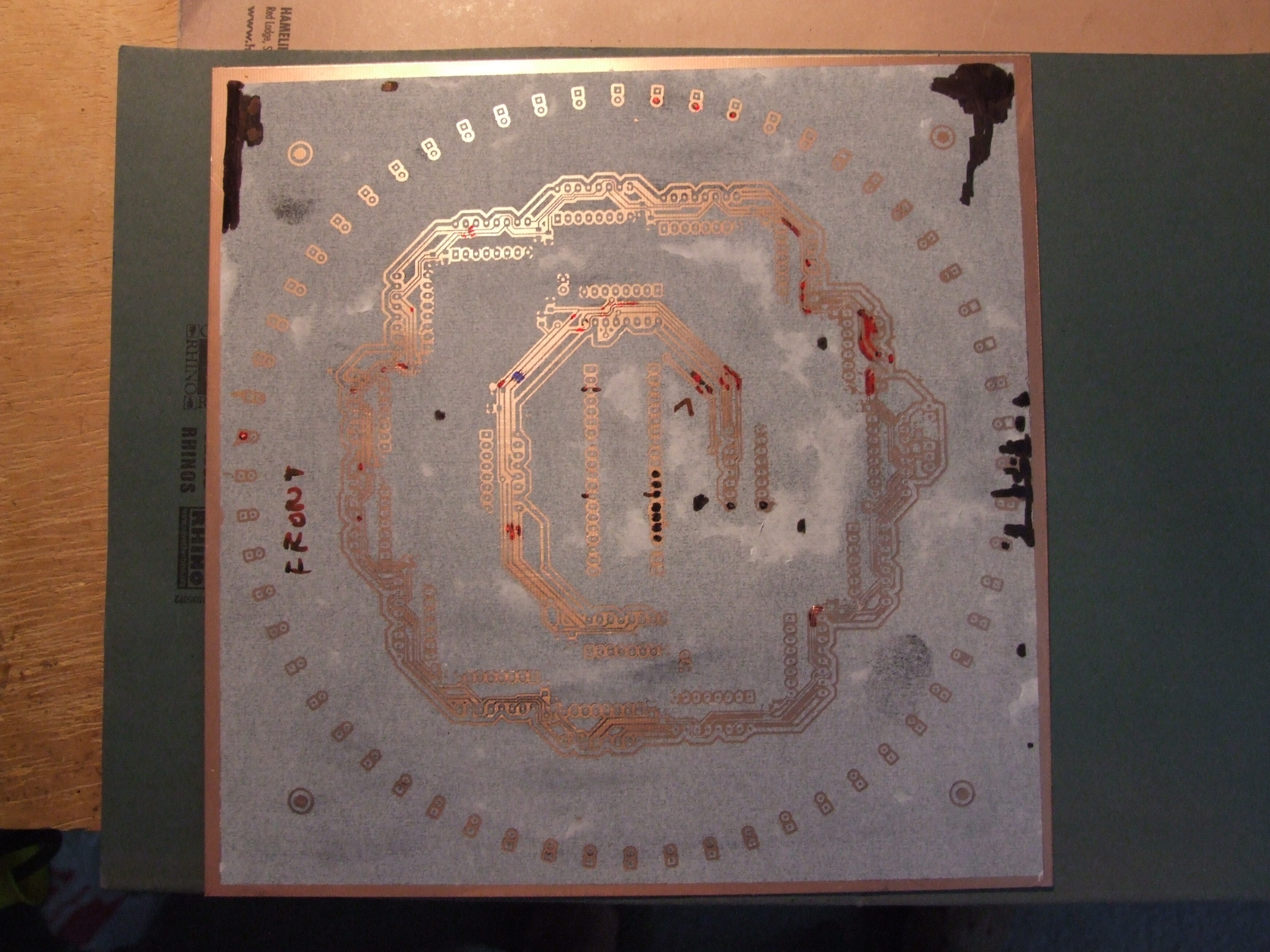
It turned out that there were other variables: the paper shrunk under heat, but I’d already ironed one side and drilled all the holes. Fortunately the tolerance was still just about on, but the other side had to be shrunk in the oven until it fitted the board, then aligned and ‘glued on’ with the iron really quickly to make sure it lined up, and then ironed all over. There were a few failures and a lot of annoyance: just getting the toner on the pcb and the holes drilled took 2 days.
Then there were the dropped tracks. The front was pretty good, but almost a third of the back needed touching up. For another day I went over every track with fine sharpie and magnifying glass, painting on the extra tracks:
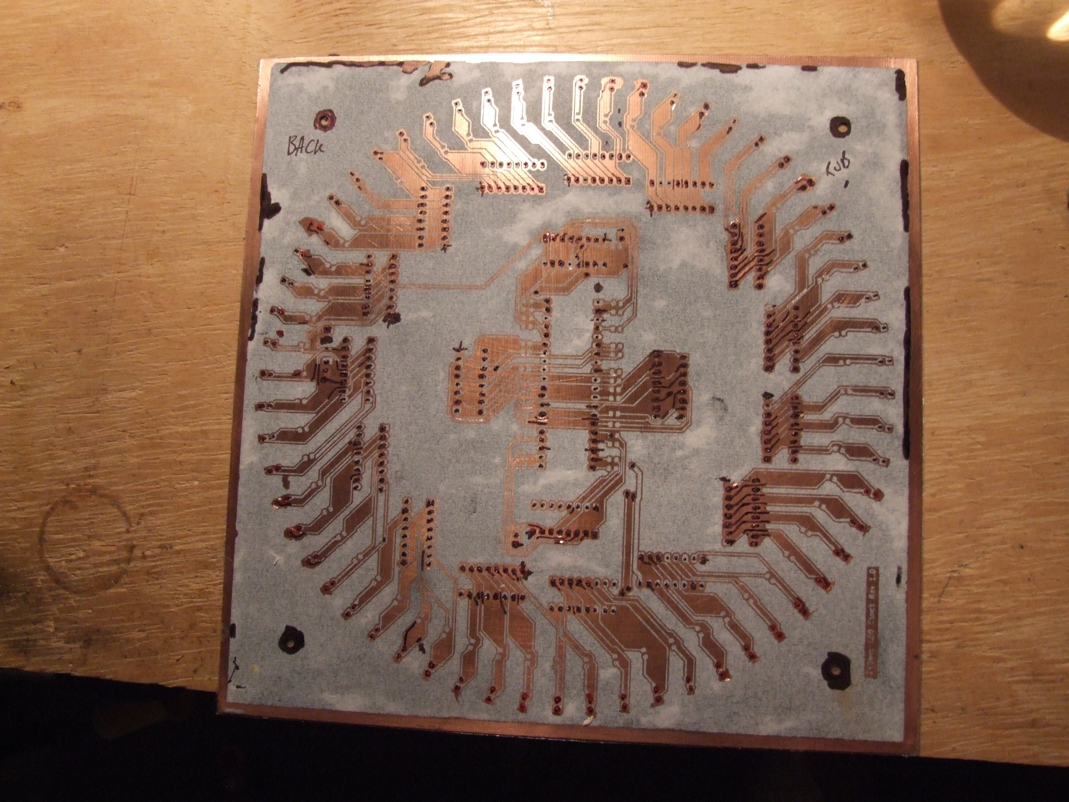
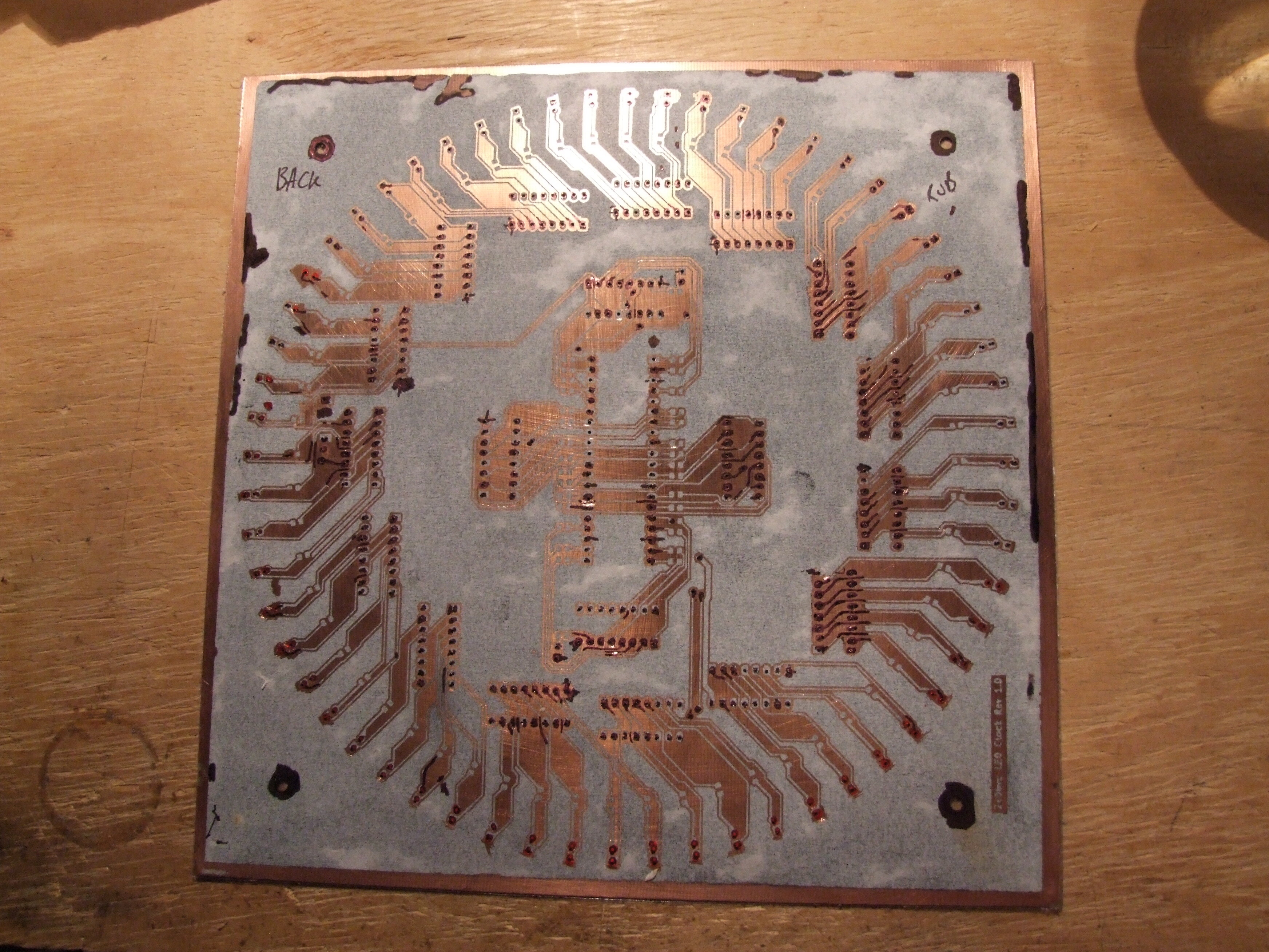
Then it was checked and checked again, and finally placed in the vertical etching tank at some unearthly hour of the night. When the board was cleaned it looked pretty good, but back at the bench there were broken tracks everywhere. Another day or so went to bridging them all with really tiny bits of wire painstakingly soldered on top:
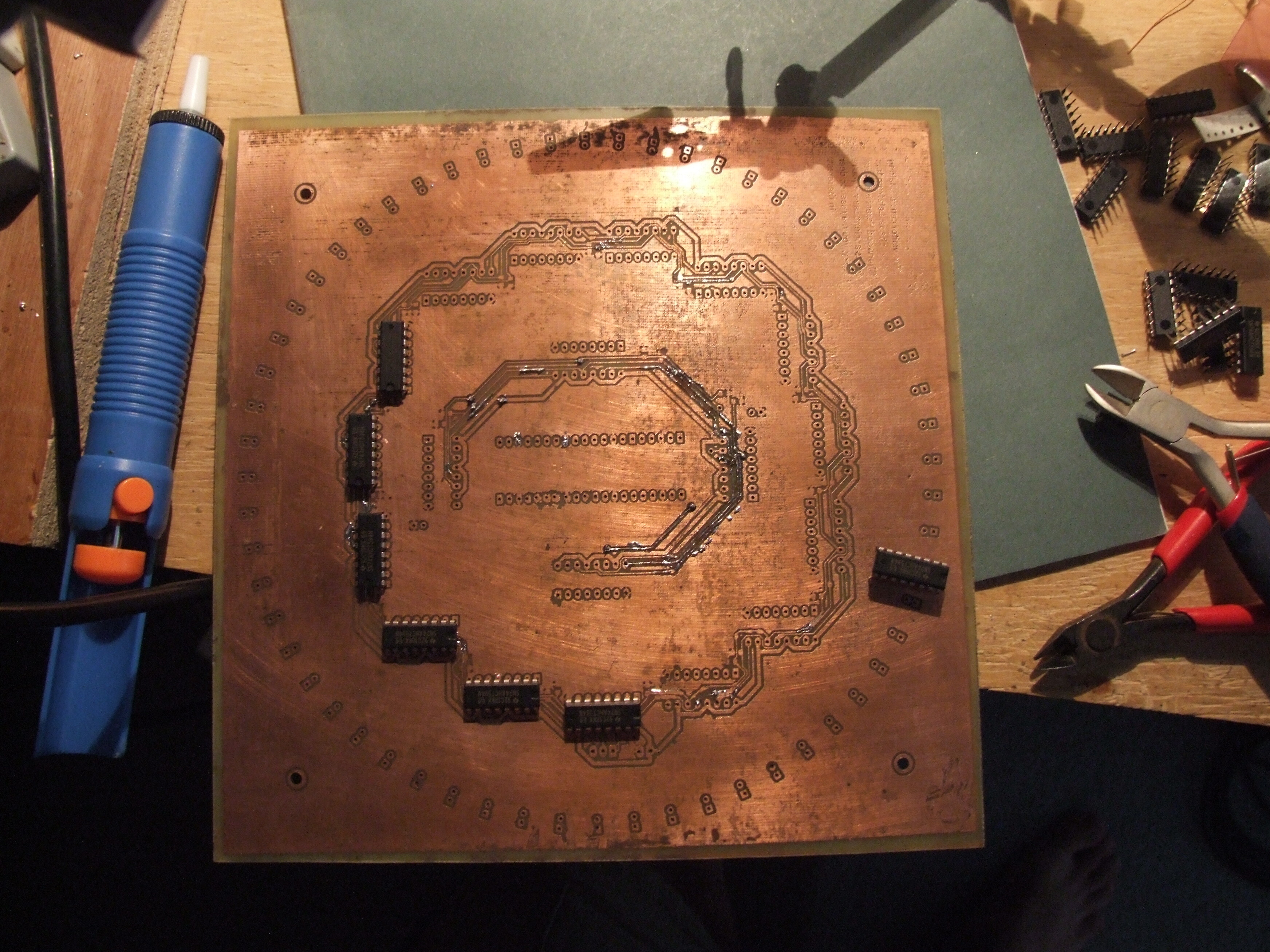
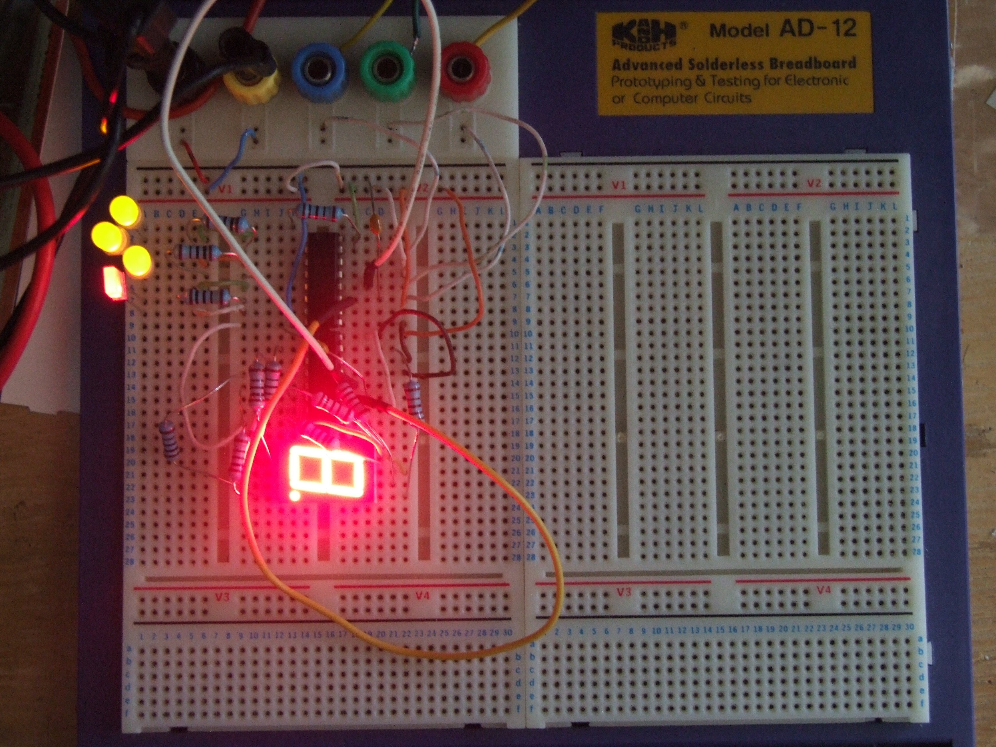
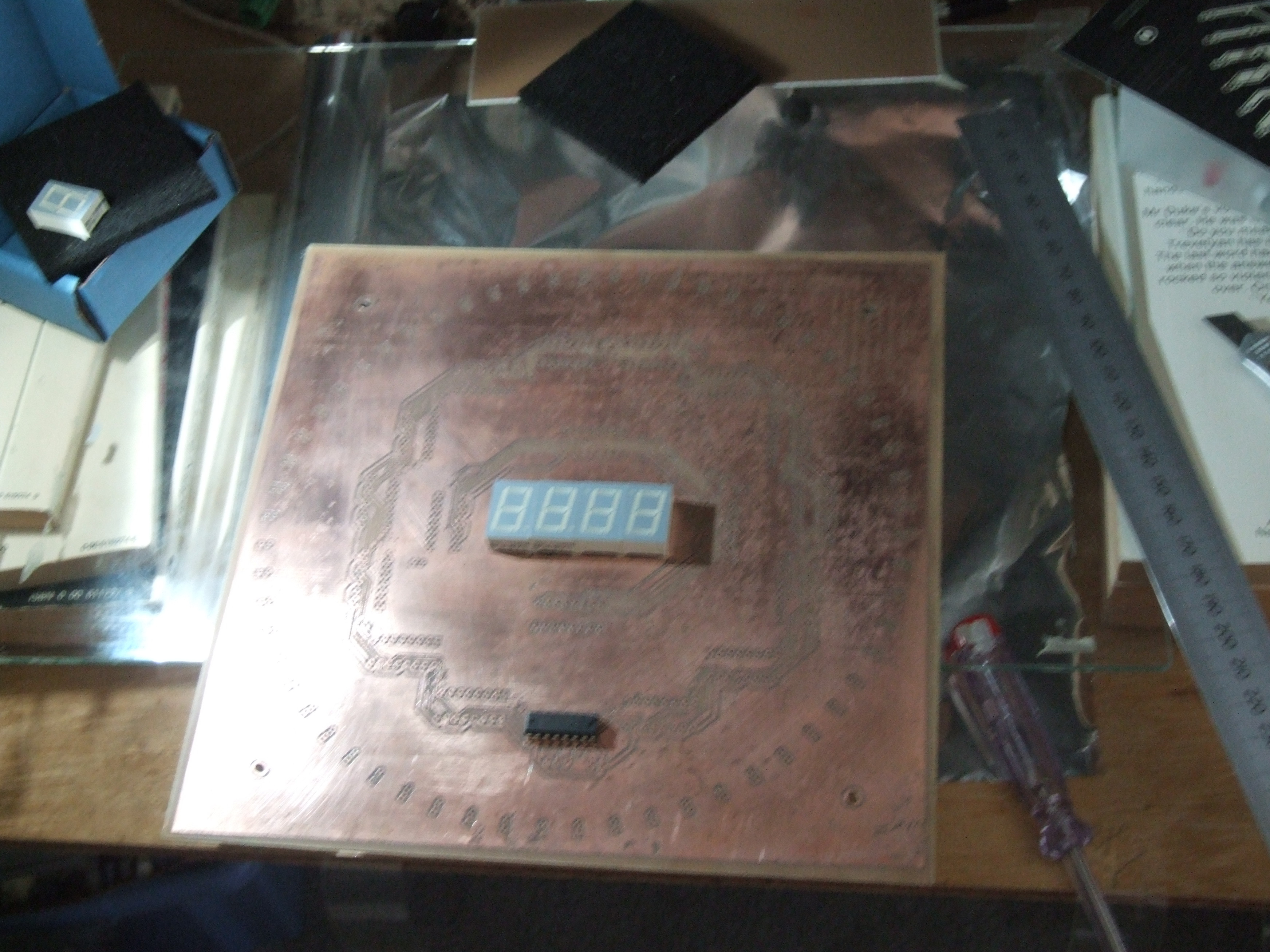
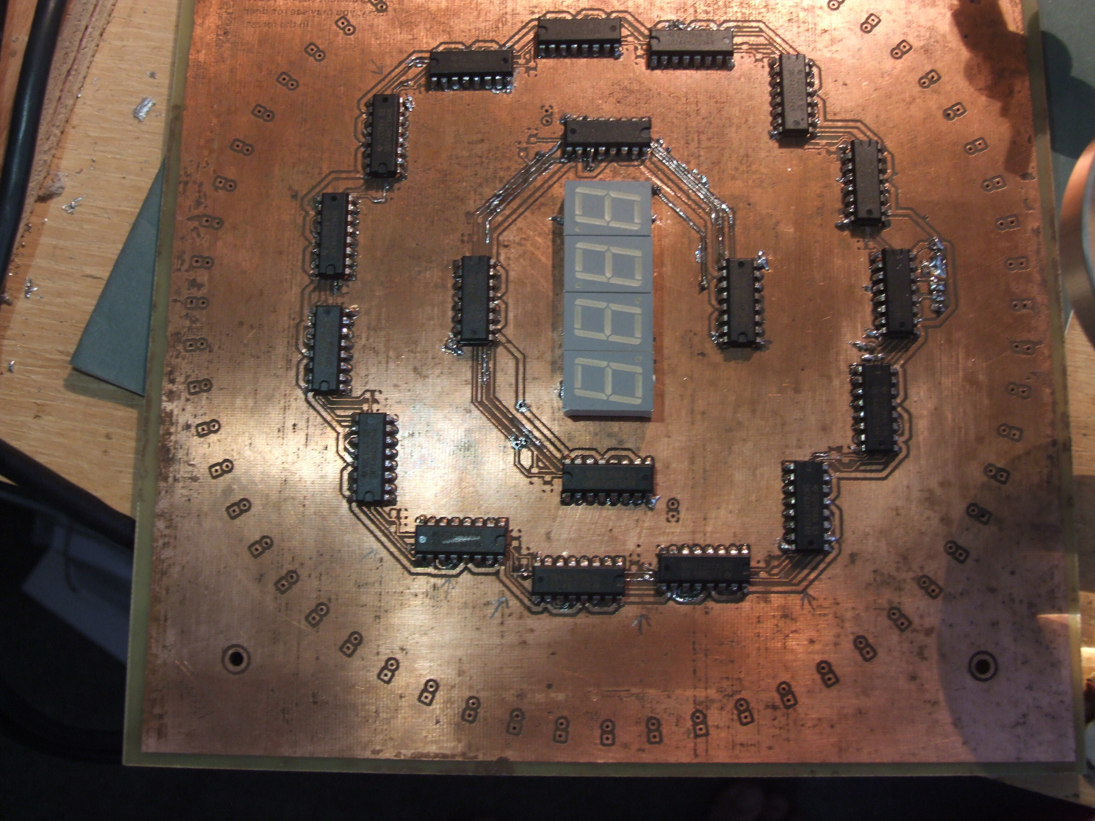
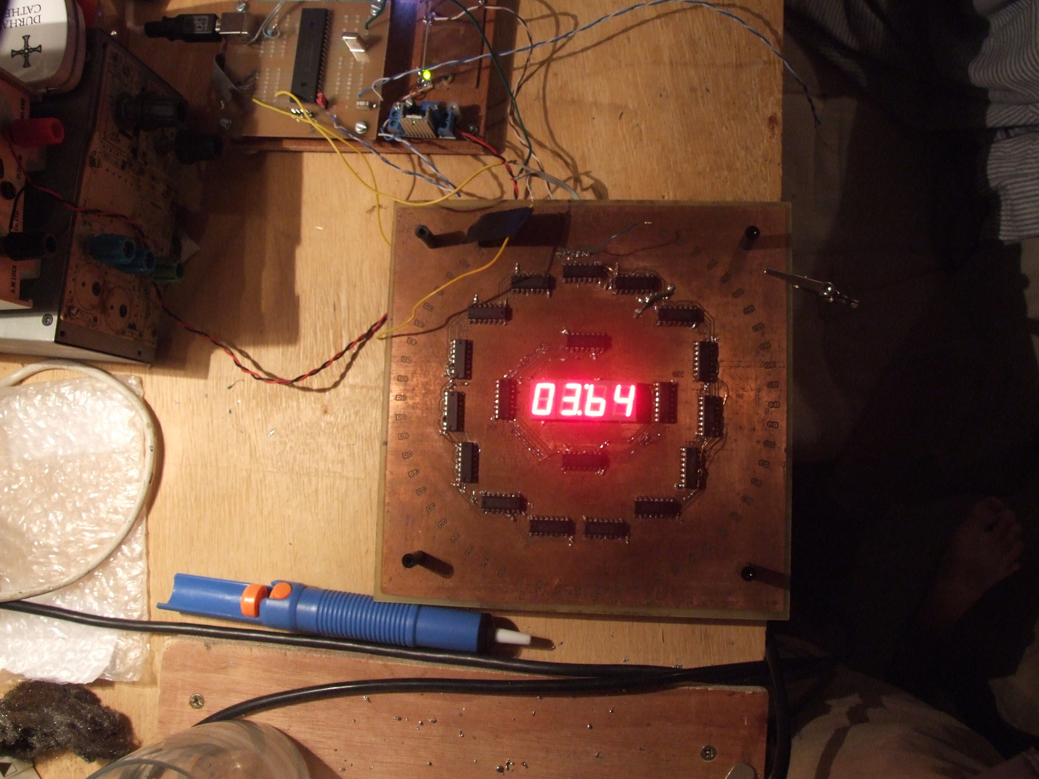
Then the resistors (0805) and the ics, and at last the final 7-seg displays to test it:
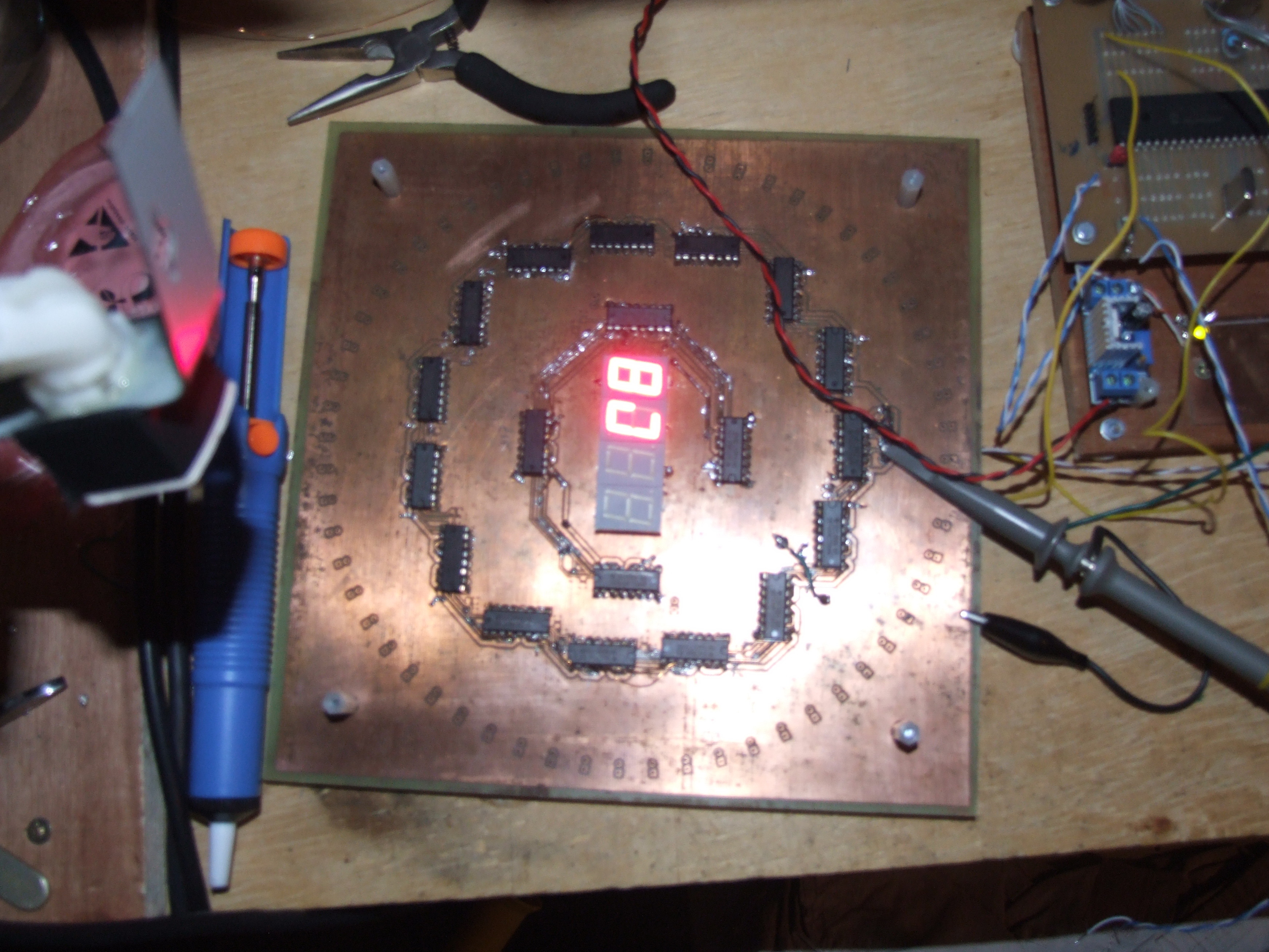
The result was a complete failure. I was testing with a Pinguino board, and even with the serial timing turned far too slow to update a clock I only got random noise out. To begin with nothing came through at all: broken tracks had slipped through. Then it things came through, but bore no relation to input. Scope probes on the lines and repetitive signalling (oh for a sampling oscilloscope!) showed phase errors creeping in from about the third IC. Google, and the discovery that I’d done it all wrong.
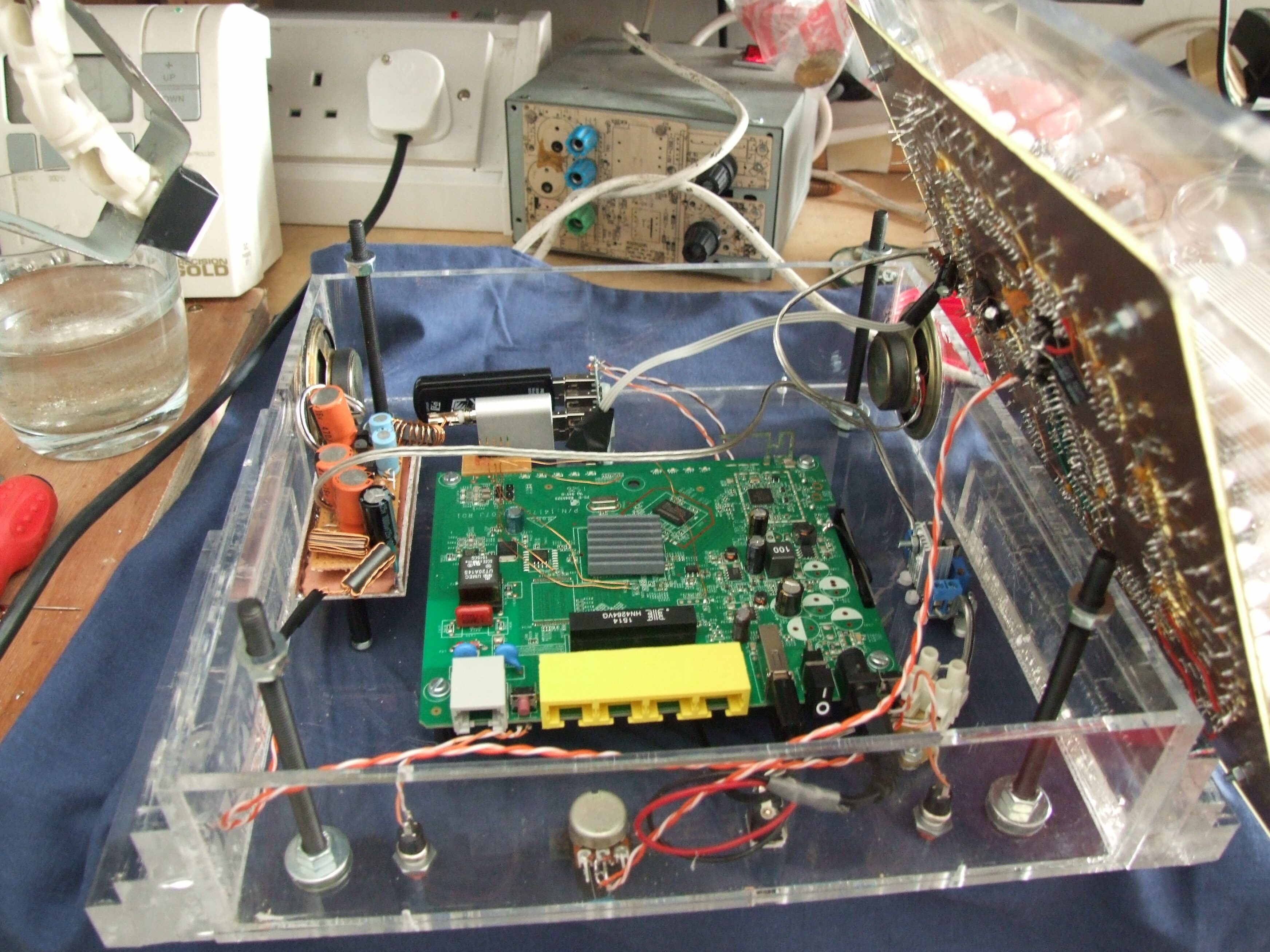
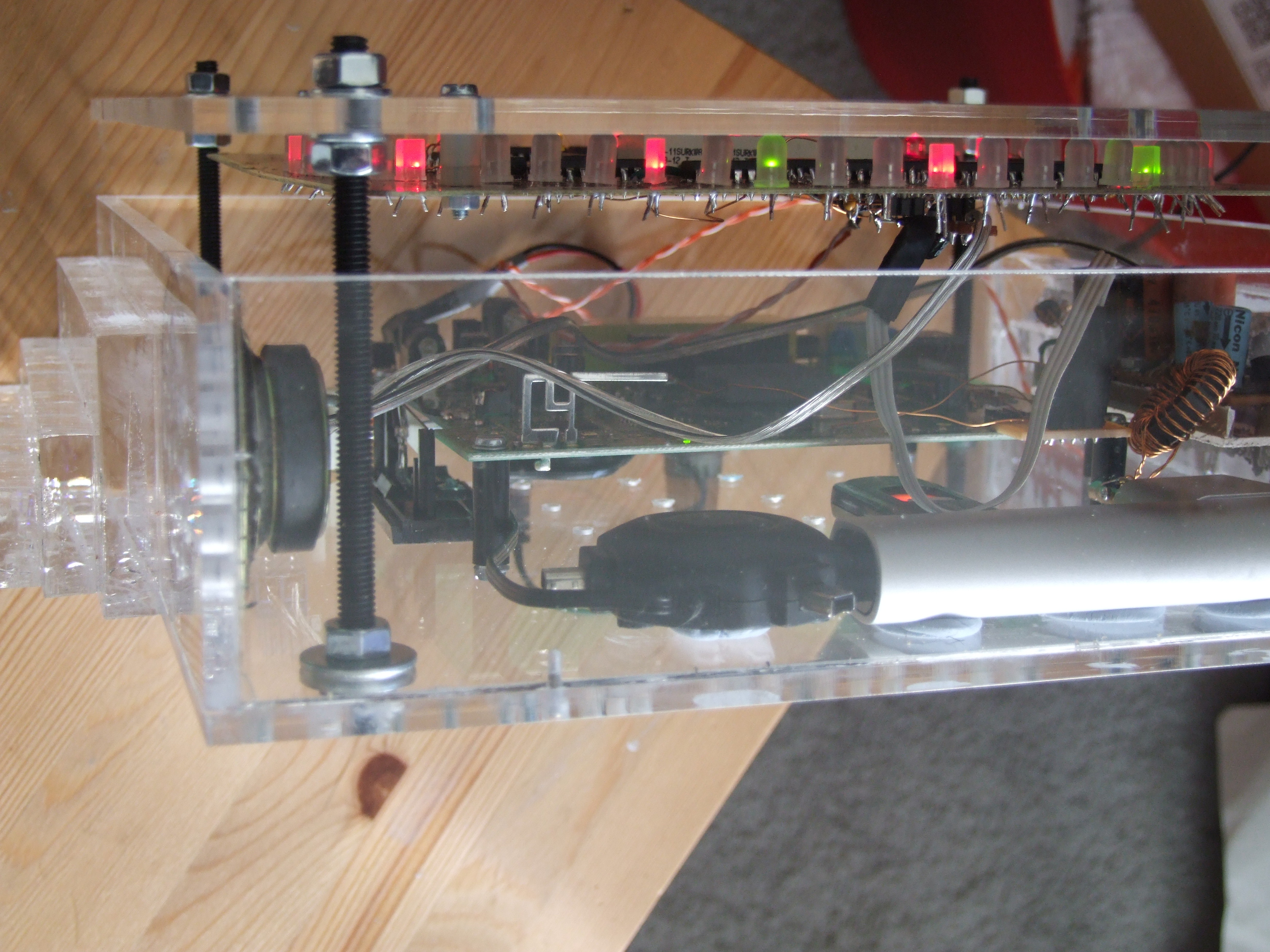
I cut all the clock lines and tried clocking the last two ICs individually from a schmitt trigger: they worked. So the display was divided up and two schmitt buffers (I think) wired ugly-bug on the back, alongside much larger smoothing capacitors, and capacitors were added accross the data line to decouple it. The clocks were fed backwards, and some of the dodgy tracks were replaced with wire. After two days it worked, both with the Pinguino (5v) board and, importantly, with the OpenWrt-running router:
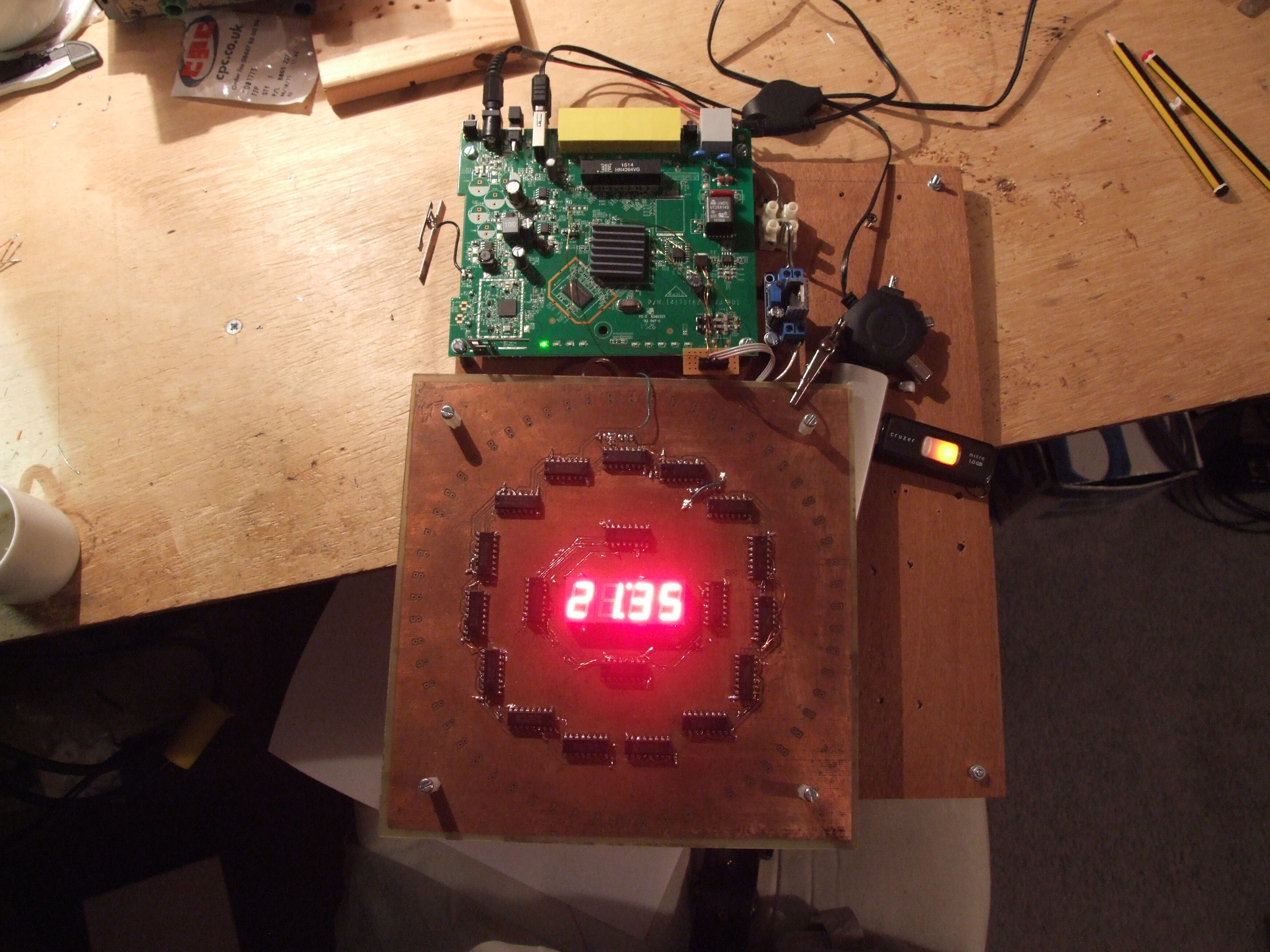
Then the leds could be added, to reveal further broken tracks. Then the LEDs were far dimmer than the central digits, and I cut the latter’s ground and inserted a mosfet switch for PWM, which worked fine with the Pinguino but later proved impossible to do reliably with the larger board (no integrated PWM was available, and bit-banging was too unstable, causing display flicker), so a 555 timer was added on the back of the board.
Amplifier
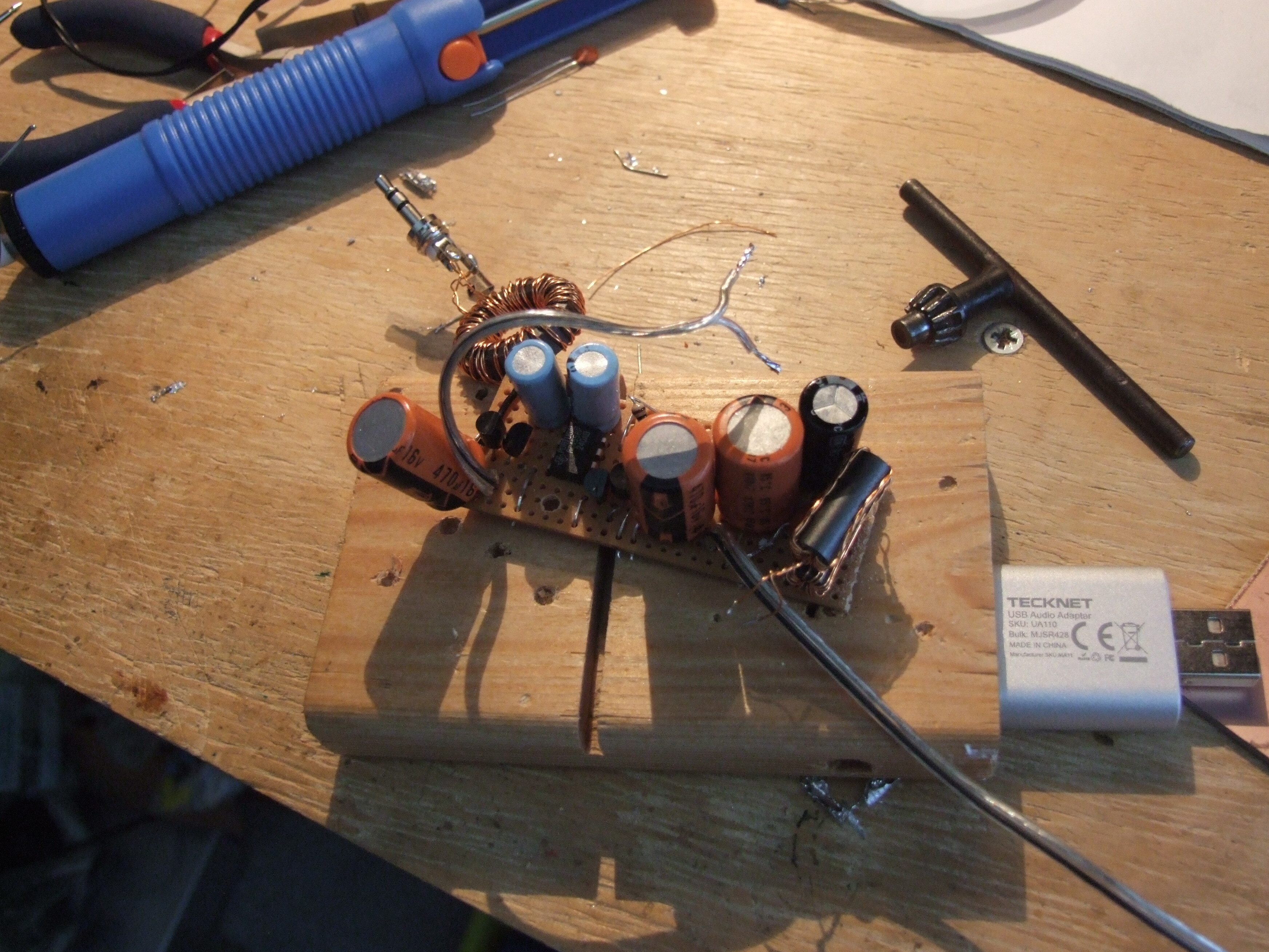
I’d ordered a stereo class-D board (which are now available for ~£1 on Amazon), but it didn’t come in time, so I threw together a basic op-amp-with-pushpull-pair with heavily filtered inputs, mounted in a shielded tray of pcb. It isn’t capable of much power (the output stage is bc547/557) but it does work, and since the chime has not actually been used has remained unreplaced:
Case
I spent most of the planning time trying to think up a design simple enough to be buildable in a hurry, and yet sufficient to offset the face and give the clock some grandeur. The final design is based on ’the’ art-deco clock, and was fairly heavily modelled to get the proportions right, but I’ve lost the file.
When the perspex arrived the thicker stuff showed cracking from the bandsaw. I decided to press on regardless:
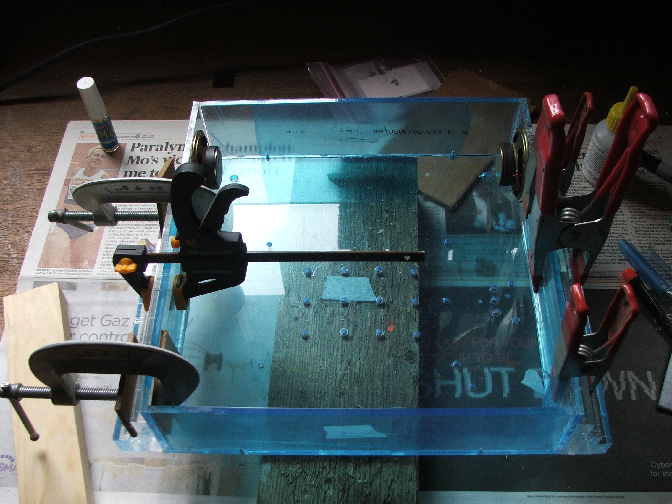
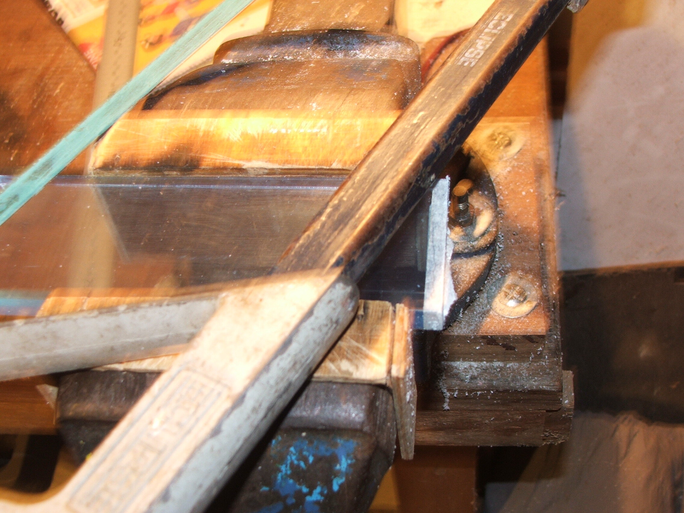
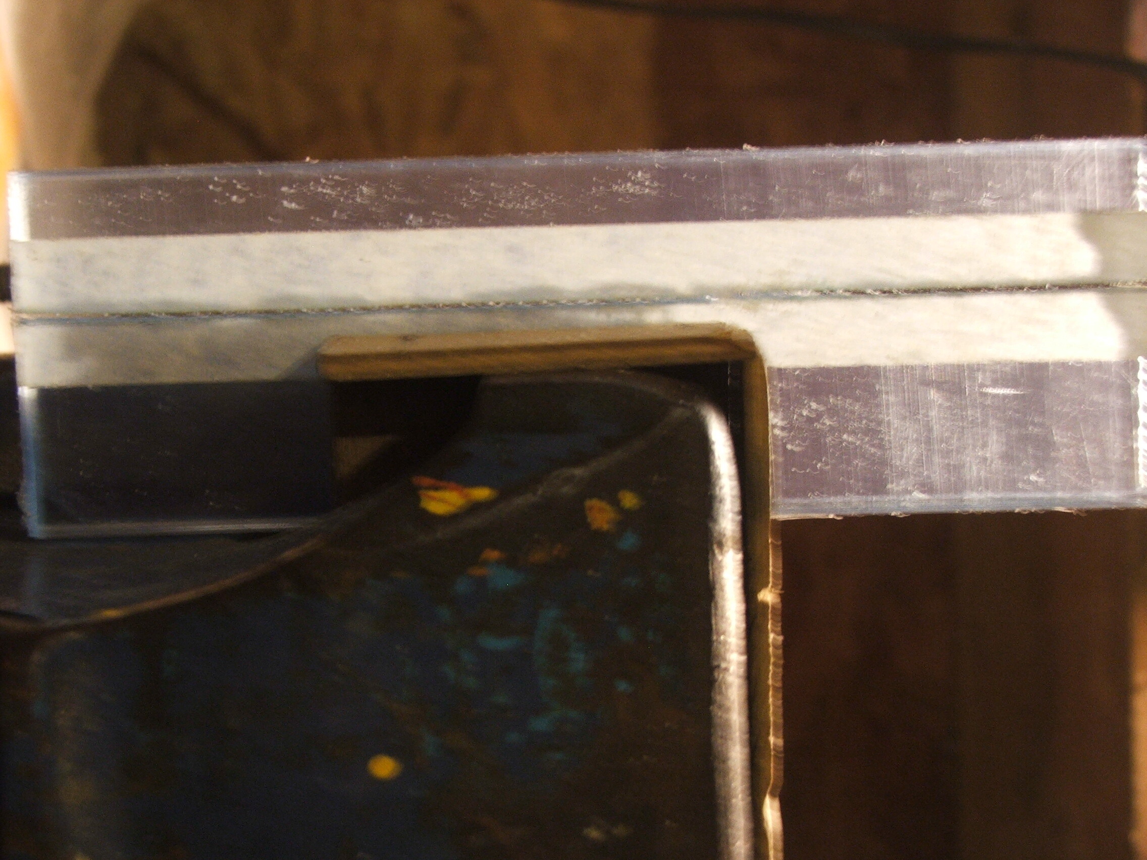
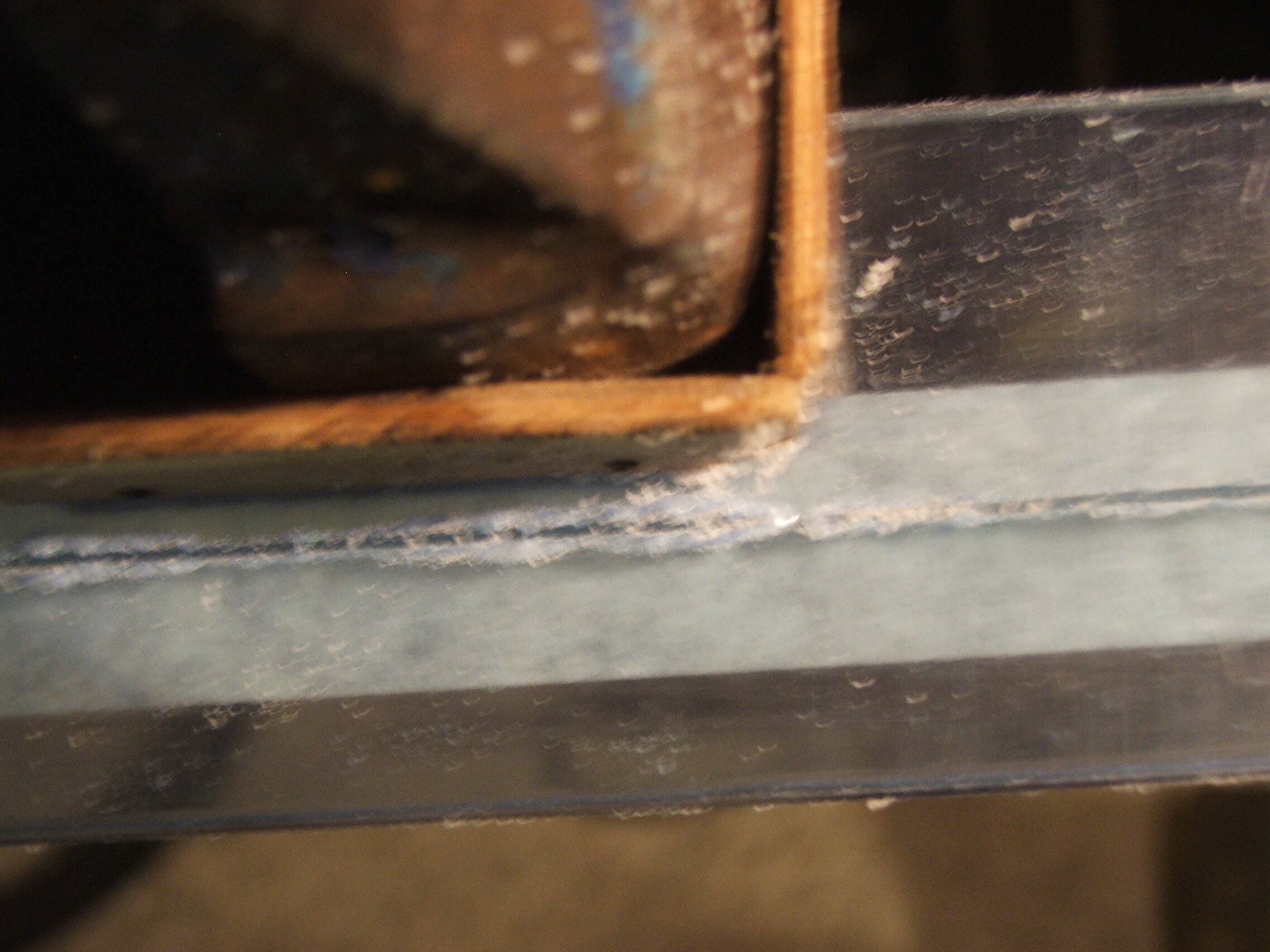
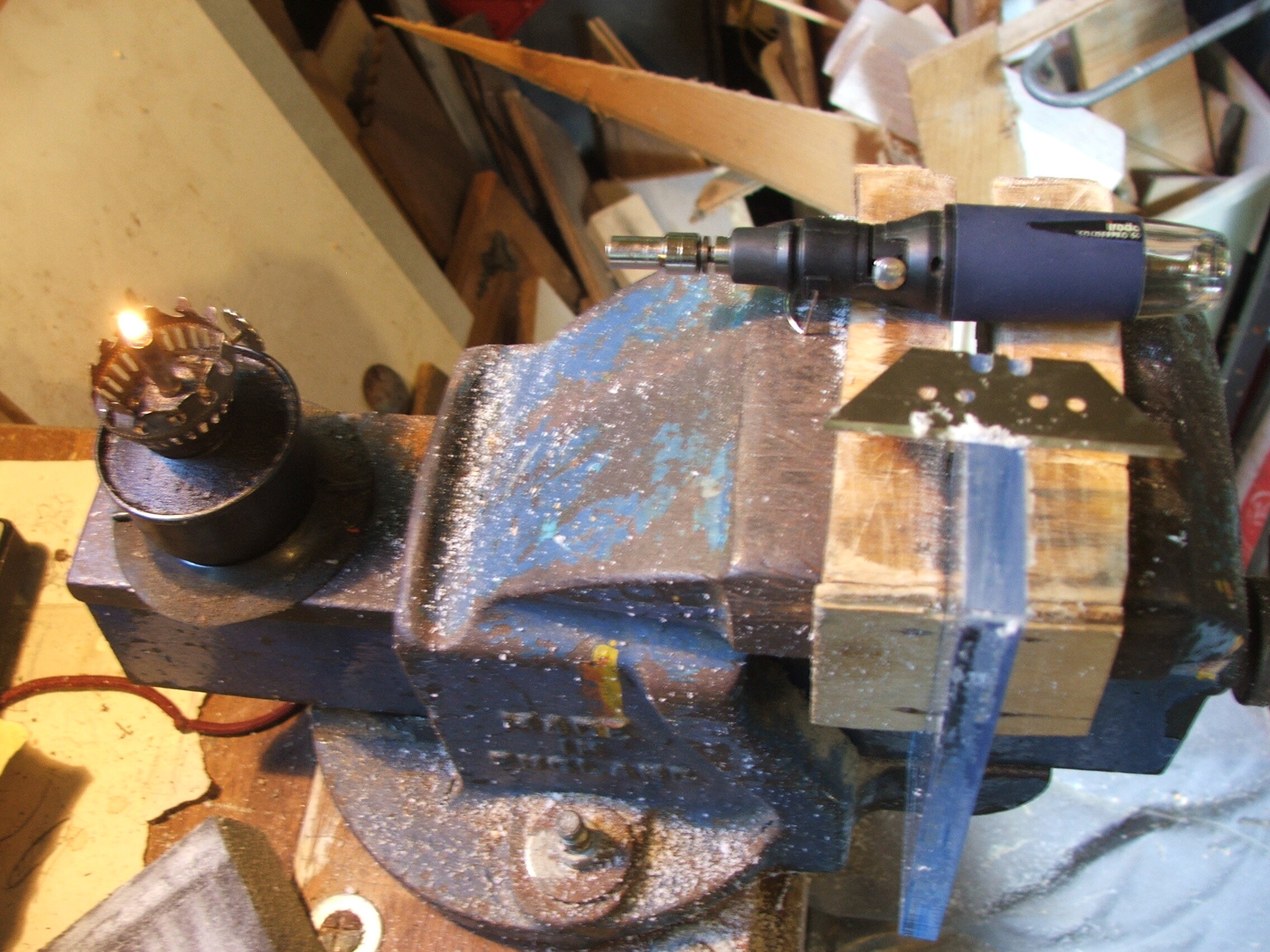
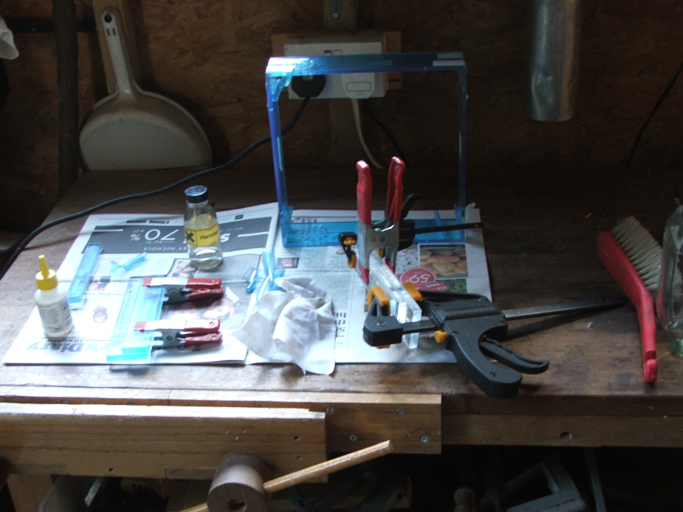
This time the edges were scraped with a stanley blade in lieu of filing, which worked very well, delivering clean flat edges before the flame polishing. The two smaller side pieces were cut in half by hand to save money when buying the plastic: I’m quite pleased with the accuracy. Then gluing up with superglue. Unfortunately the superglue fogged inside the cracks, and they stand out when viewed from the side. But the effect is minimal, and face on the case is exactly as designed:
The knob on the rear controls the brightness of the central digits.
Software
This clock uses a simplified, rather cleaned up version of the code running the older clock. It has a rather basic web interface which allows one to change the colour scheme used by the hands, blank the display, and adjust most of the runtime variables. The web interface is thrown together in PHP and uses a unix FIFO to communicate with the running python program; it’s rather overkill for a clock, but it works. There’s also a PHP interface to the mpd server from one of the myriad of abandoned static clients on github, although the alarm and chime functions have yet to be used. The code is once again online for those who want some amusement. This time round I used a more up-to-date version of OpenWrt, with better wifi performance, and a gpio library which seems to write better than the pseudofiles. The board can be updated in .4s, but for reliability we slow it down and take .8s. An unforseen consequence of those tiny bits of wire repairing tracks is that they act as little speakers, contracting and expanding with the data. The worst offenders were glued down, and the noise is minimal when the case is assembled.
Since it’s been in the living room I’ve spent far too long watching for display glitches, but so far I think I’ve seen one, maximum, in a total of several hours’ observation—and I may just have blinked. The chosen colour scheme minimises current consumption, but it is possible to have more blinkenlights.
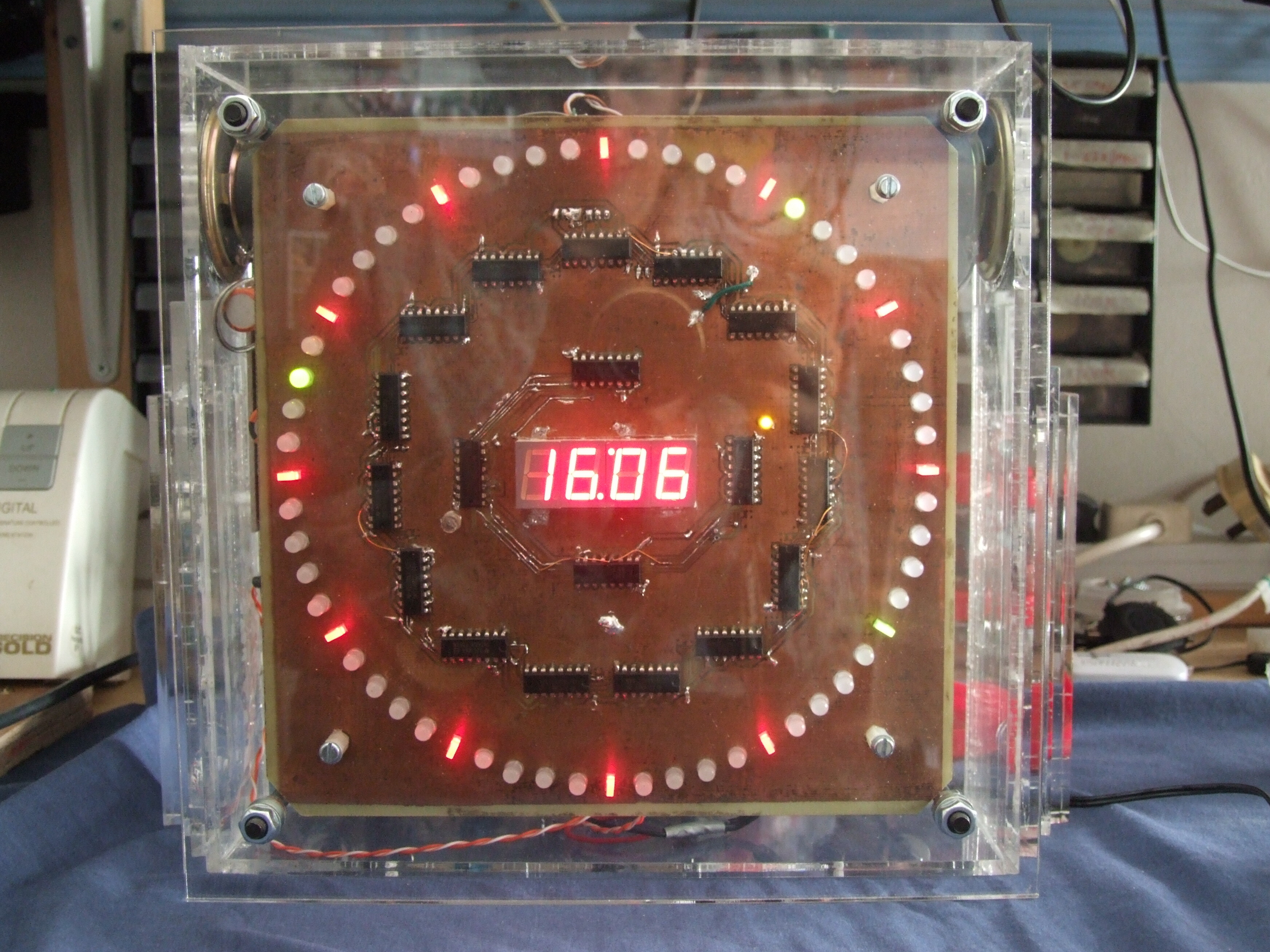
In use, the second is easily read. For the other hands it’s quicker to read the central digits, although looking a little longer shows where they are.
This is easily the best clock I’ve made, and other than a possible repeat with a Raspberry Pi Zero (£10!) board driving it and updated front board, I’ve no plans for any others, at least of this kind.