This was a sudden impulse last summer: I’d seen a ‘sunrise’ alarm clock (which fades on slowly to simulate sunrise, theoretically bringing you out of deep sleep naturally and waking you up gently). My sister mentioned having difficulty getting up and needing multiple alarm clocks. Ergo.
First thought: where to get the light? I had a look in the LED parts draw, but it was disappointing, as was the draw of old led torches and bike lights. None of them gave a reasonable light: more like a little pin-prick than the sun. So off down the road to the bricolage shop (or bric-a-brack as we call them) and I came back with this:
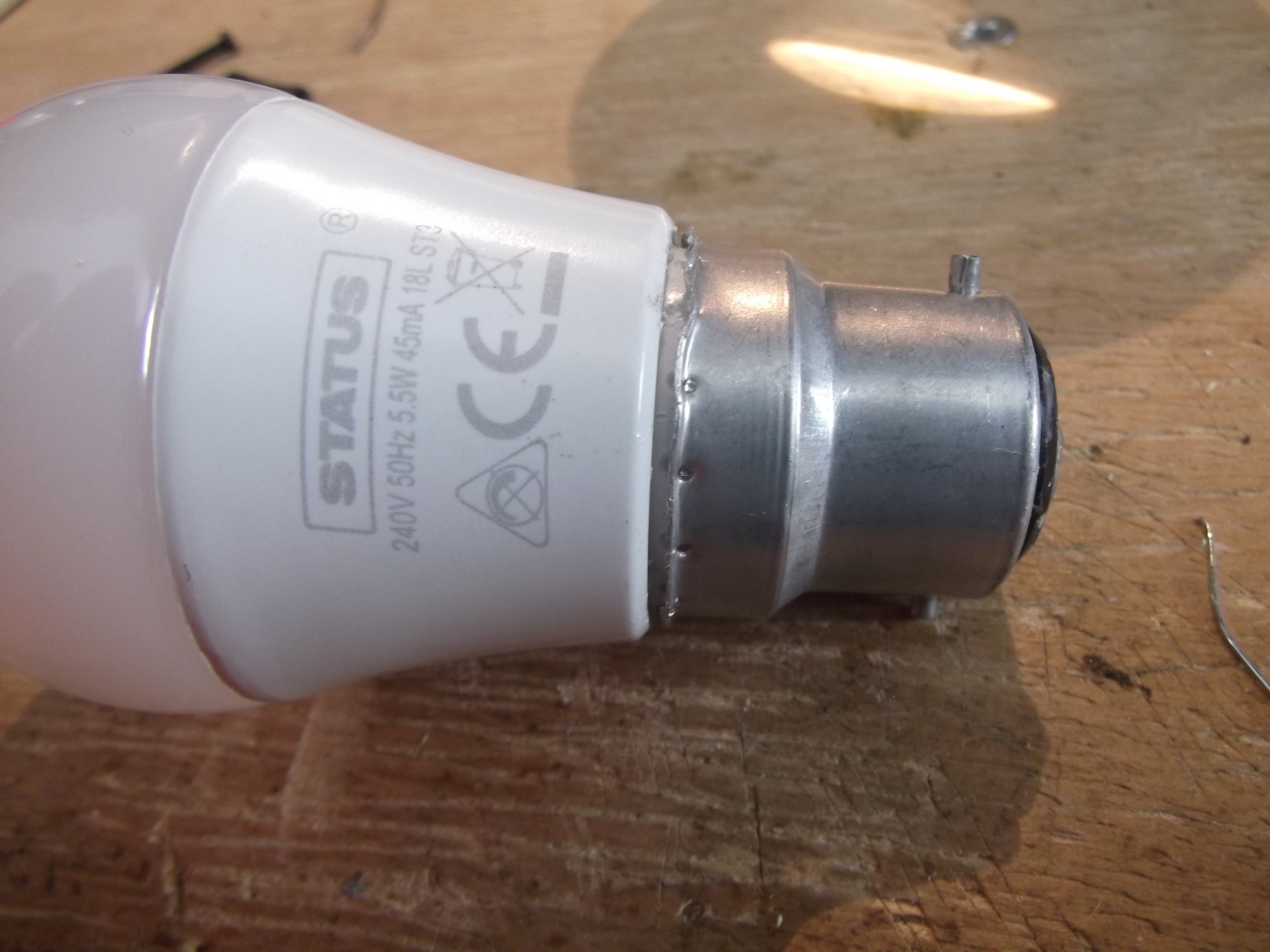
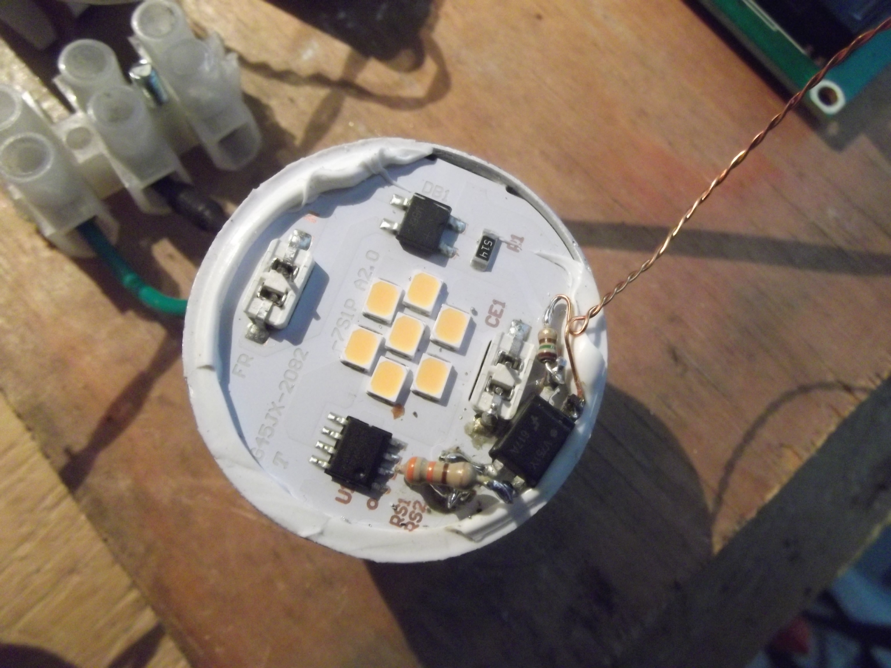
It’s a standard ‘40W equivalent’ ‘golf-ball’ led bulb. I’ve started prying off the BNC cap, as you can see. Here are the internals:
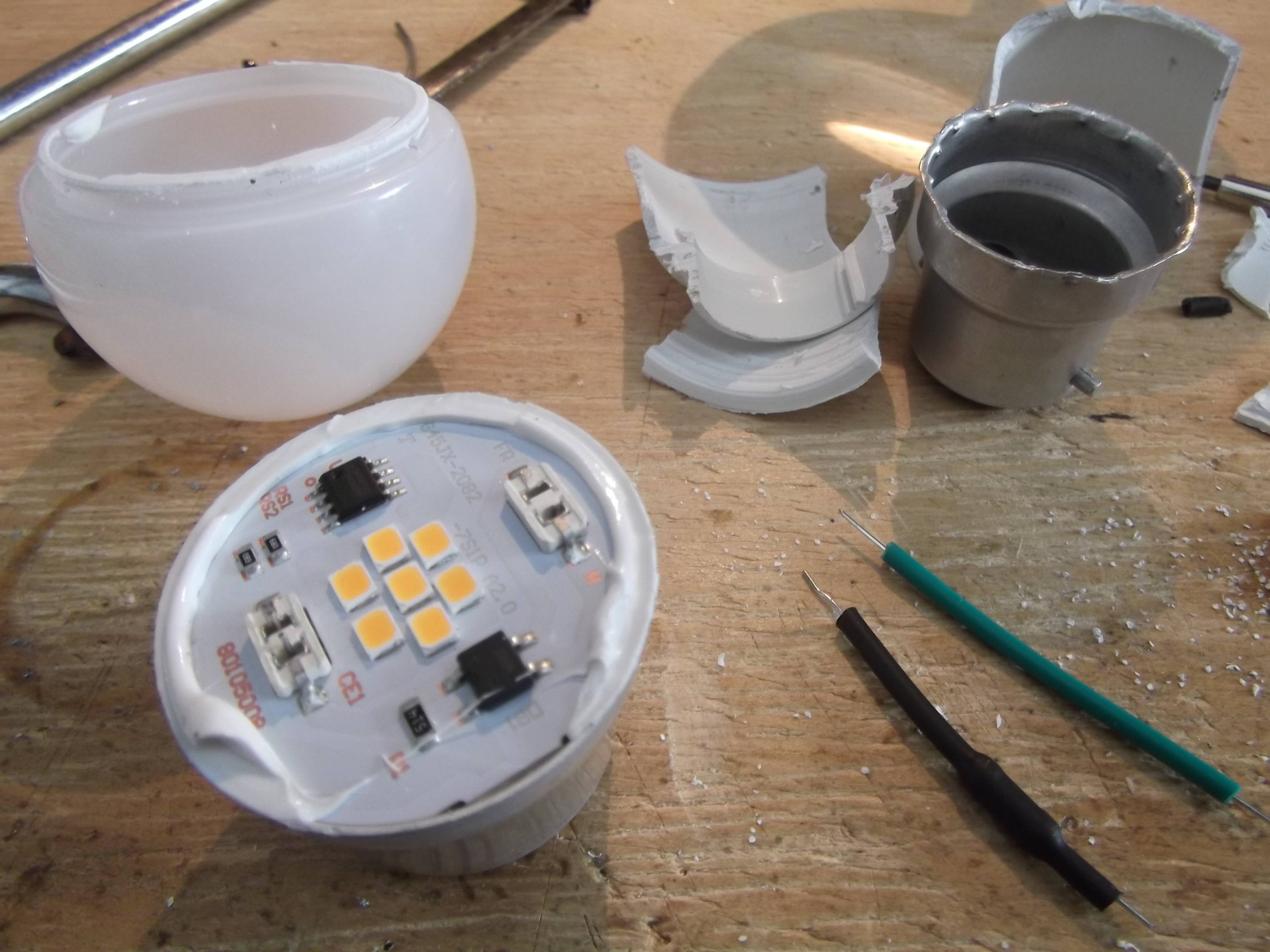
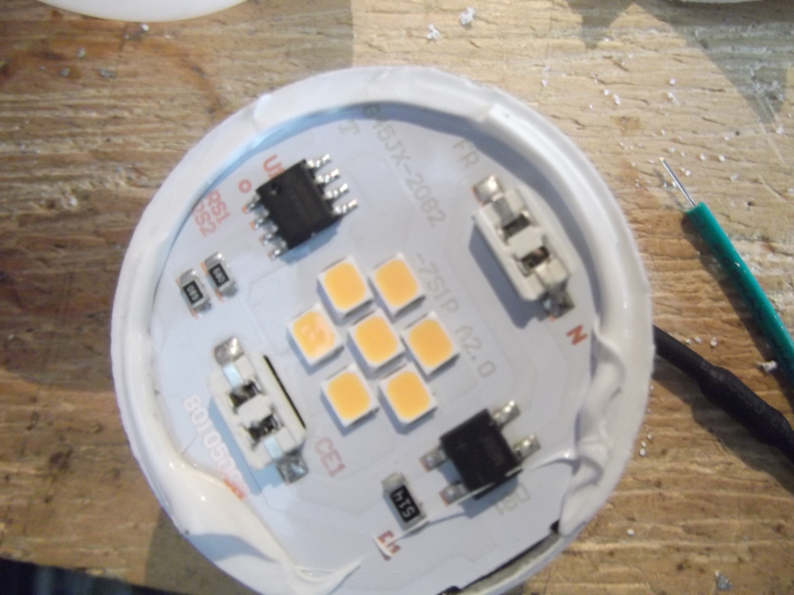
Top is power in. It goes directly to the bridge rectifier (bottom right). Ater that is a chip capacitor in parallel with an electrolytic, and then the voltage is fed directly to the regulator IC, top left. Below the regulator IC is a pair of paralleled current sense resistors, which set the output current. The output of the IC directly feeds the LEDs.
Note what is not there: there’s no EMC protection anywhere (lower power devices are frequently exempt—unfortunately). One of the wires connecting the board to the cap has a fusible resistor inline; this is all the protection it gets. I expect the IC has overvoltage protection. There’s no inductor or LED-side smoothing: I suppose the ‘regulator’ just does crude PWM directly on the mains input, which probably shortens LED life. Disappointingly, the regulator datasheet does not mention anything about a PWM input to control brightness, which some of these ICs have. I’d hoped to get lucky; oh well.
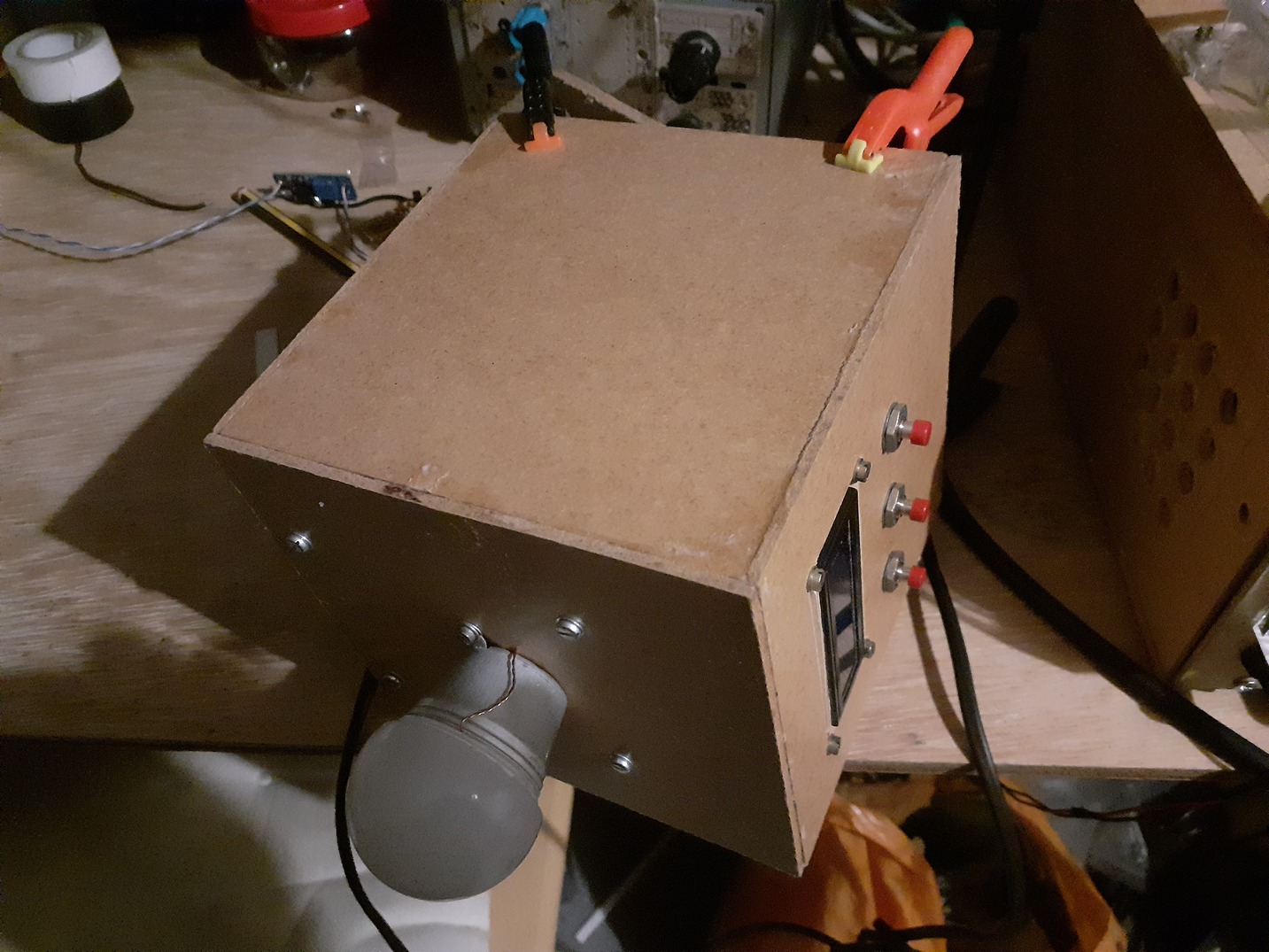
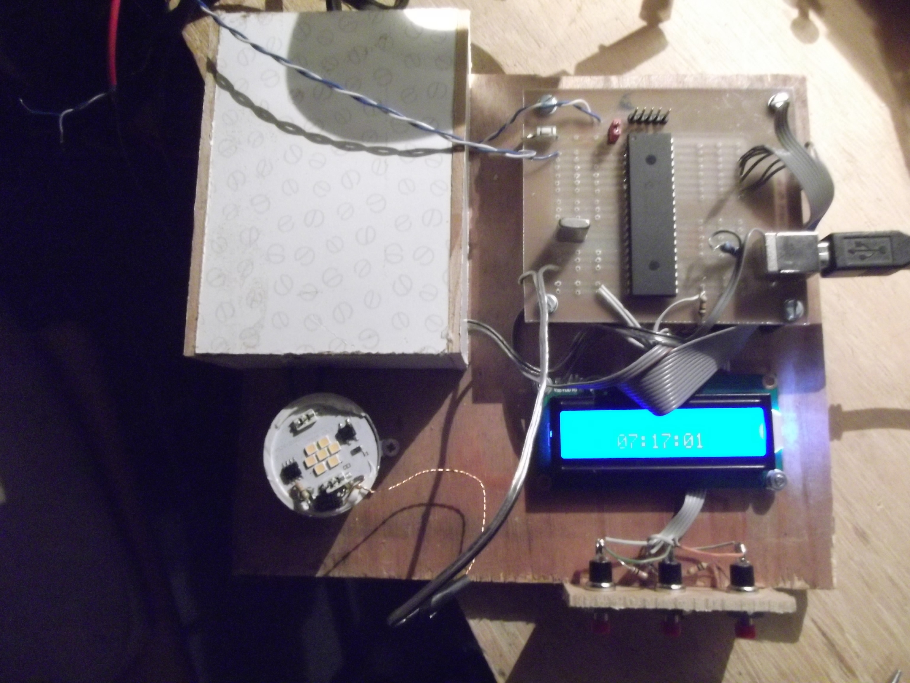
What happens, then, if we take the current sense resistors out of line? Theoretically this should result in the IC supplying no current at all. In practice, it results in the LEDs glowing very dimly. Putting various different resistors in here confirms we can control brightness from ‘very dim’ to ‘very bright’, although it’s still only a ‘40w’ bulb. The next step was to try PWM by switching the original low value resistors with a mosfet (bonding the floating ouput of a bench power supply with the IC’s internally generated vcc). For this the Pic Development Board was used. First tests were successful, so I went hunting for an optoisolator, and tried using that instead of the mosfet. It worked (a slightly lower resistor was needed, I seem to remember, to get the same maximum brightness). I also found an old wall-wart 5v SMPSU and took the board out, and a 5v relay on a board saved from an old washing machine. Putting this all together on one bit of ply with the PIC, some buttons, and a 16x2 LCD we get this:
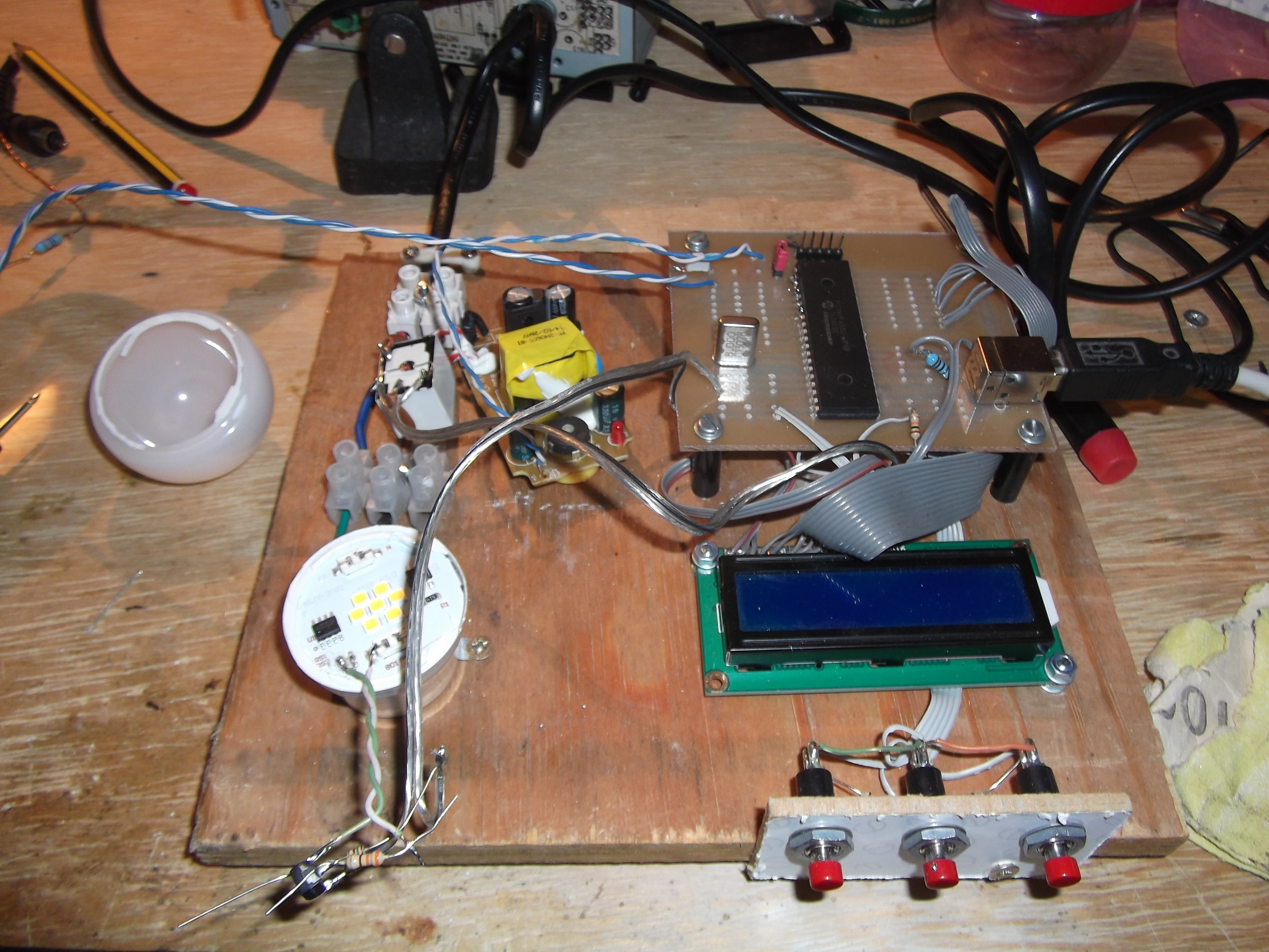
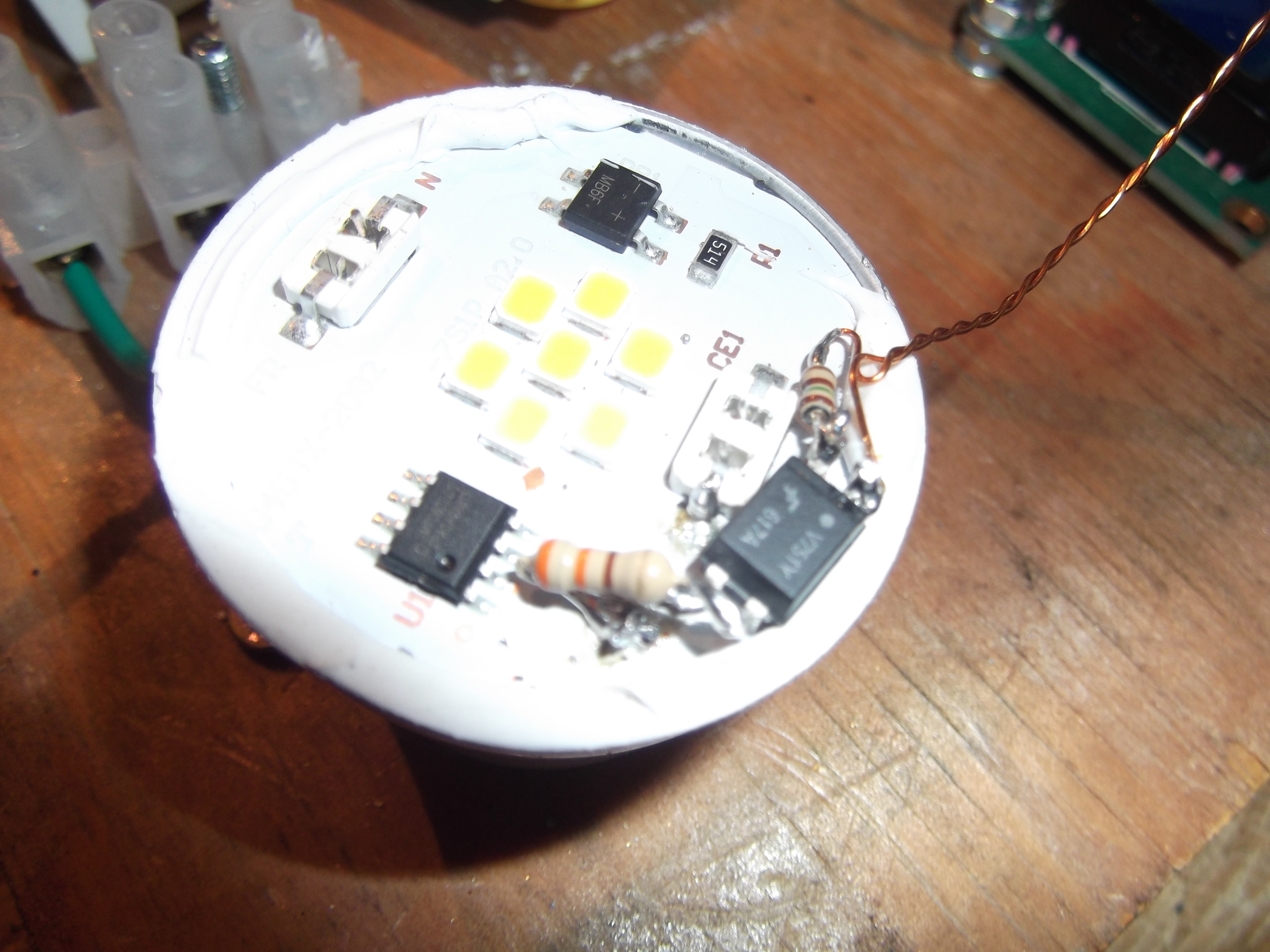
This setup lets me turn the lamp on (with the relay), and then increase its brightness (by PWM accross the sense resistor connections). A tad ugly, but it works. Then to mount the optoisolator properly on the lamp:
And box up the mains side of the breadboard for safety:
The lamp cover was later glued back on, and a piezo buzzer added for a backup alarm. The next question was the clock: I had no RTCC (RealTime Clock/Calendar) modules on hand, and whilst they’re very cheap, this was supposed to be a quick project. I do have a stock of old digital alarm clocks, which I tried to use to auomate things as a boy by replacing their piezo buzzer with an amplifier + latch + monostable which would short out a transistor accross my laptop power supply, turning it on so it would be booted by time I got up, and I could practice Morse Code. I never got the bistable latch working properly and consequently never learnt Morse properly. One of these, with the buttons shunted with transistors and the piezo taken to an analogue input on the PIC could theoretically function as an RTCC. But after all the PIC has a clock (48MHz from an 8MHz crystal); couldn’t we do the clock in software? The PIC is running the pinguino bootloader, and in the shipped ‘pinguino example’ files is something like this:
void tick(){            // function called every second
  if (!stopClock) {
    s++;
    if s  59) {
        m = 0;
        h++;
        if (h > 23) {
          h = 0;
        }
      }
    }
    if (displayClock) {
      lcd.setCursor(4, 1);
      lcd.printf("%02u:%02u:%02u", h, m, s);
    }
  }
}

void setup() {
  // put your setup code here, to run once:
  OnTimer0(tick, INT_MILLISEC, 993);
}
The value is somewhat less that 1,000ms as the PIC’s clock is not terribly precise (although it is accurate: it shouldn’t drift). As you can see, Pinguino is an Arduino clone running on PICs. This stuff is great for throwing something together; it’s less great for squeezing the last 5% out of a low-powered MCU. It’s also not very actively developed and the ‘ide’ is a nuisance which plays poorly with tiling window managers. But somebody else has done the work, so I shan’t complain. That’s also bad C and bad MCU writing, but that’s largely my fault.
The rest of the code is very easy: we need to check for alarms (a simple flag in the tick() ISR is fine), write the time, and fade over periods. Everything was done asynchronously, which works—providing the lcd isn’t being written to when the ISR triggers and starts writing, or else it prints nonsense. This race condition bug is embarassing, but it took ages for it to occur (luck) so I didn’t think of it until rev. 2.
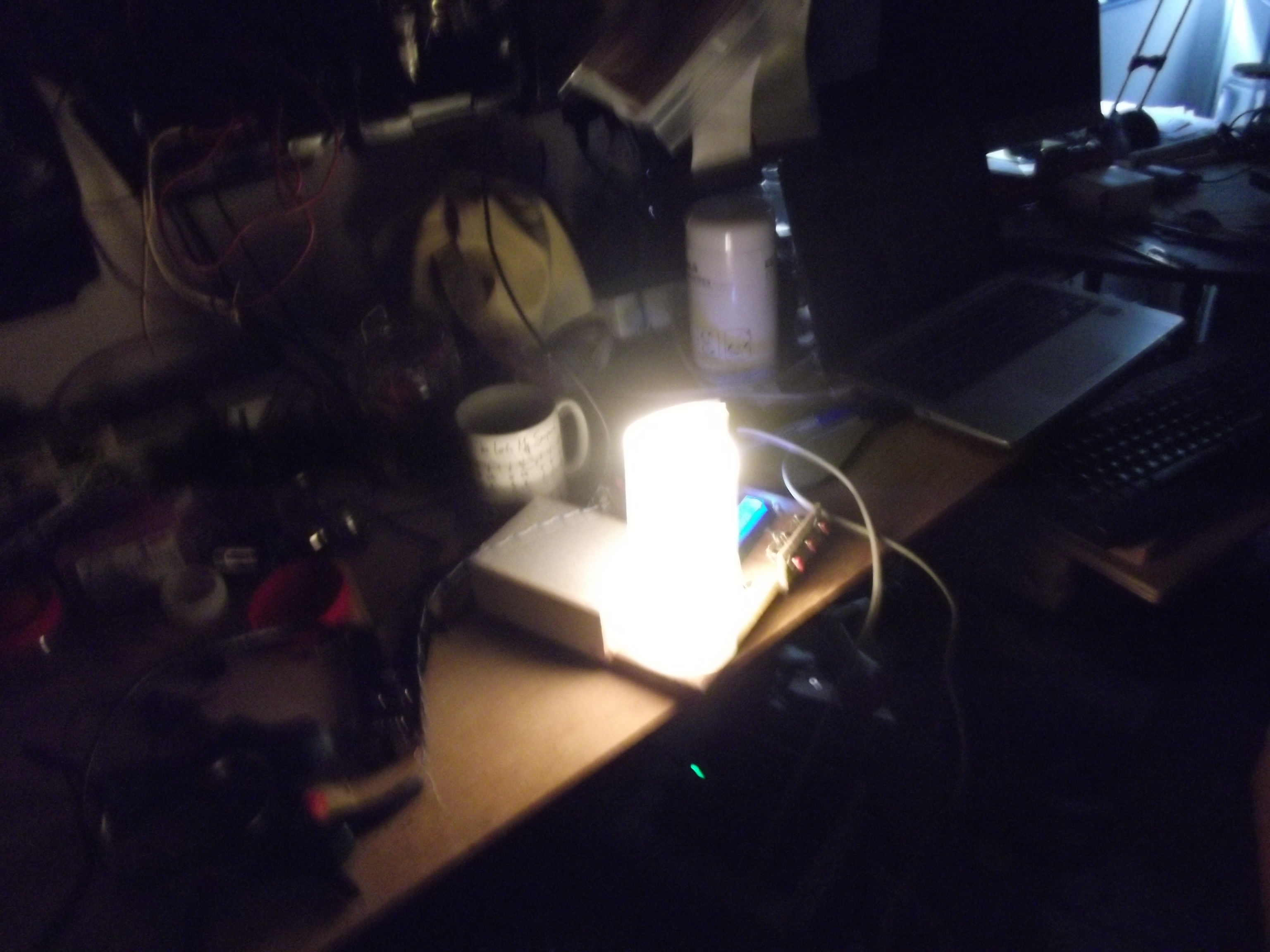
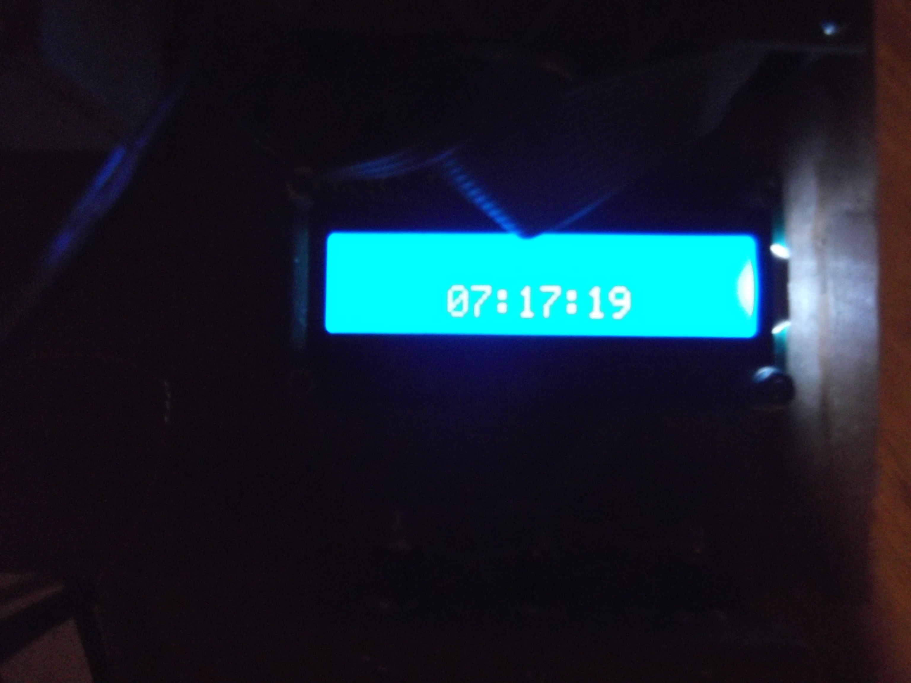
The lamp was PWM controllable by the end of one day, and the pic was behaving itself the day after. A competent MCU programmer could have thrown the whole thing together in an hour. Here’s a rather blurry pair of photographs showing a test, on the left of the lamp, and on the right of the clock’s rate.
The hardware has been in use since the summer, and has apparently had a noticeable impact on how quickly my sister wakes up, so that’s something… No code online as it has been entirely rewritten.
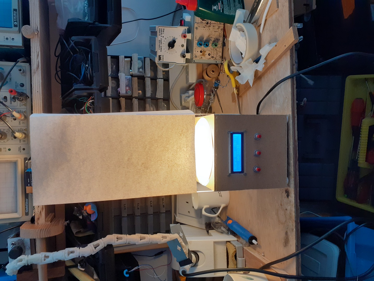
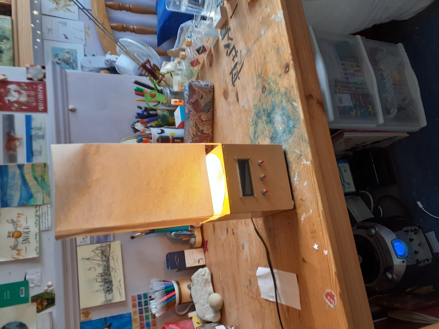
Addendum: Case
Eventually I got round to making a basic hardboard box to put the lamp in. Here it is, looking a little more like a real lamp: