Every project is a prototype, which calls out for a second version avoiding the mistakes of the former. The trick is to give the prototypes away; then one has a legitimate excuse to make another—and one gains an (undeserved) reputation for generosity to boot. After the quick sunrise alarm clock various things happened, including a ’two week lockdown’ to build up capacity in the NHS, which turned into three months. Thus I was stuck in one part of London, and my fiancée in another, and the streets were patrolled by Dobermans with £10,000 fine notices stuck to their teeth. How to get from one side of London to the other?
Fortunately in the Lockdowns we learnt that the menial classes (i.e. pizza-delivery men, bus-drivers, cleaners, plumbers, gardeners, bin-men, the people who stick those flyers through the letterbox which nobody reads, etc) were immune to the plague and thus could be allowed to bring us pizza, clean our houses, take out our bins full of ’essential’ Amazon supplies, etc, without catching the plague and dying by their thousands.1 Meanwhile we, the at-risk young, the dangerously unfit middle classes whose gymns had been closed (et cetera, et cetera) could protect ourselves by staying at home and ordering takeaway pizza and new toys from Amazon. And in this way we all battled mightily against the plague, ‘The rich man in his castle/The poor man at his gate’.
Thus clearly the trick for getting across London as a detested member of the bourgeoisie2 was to dress up as the proletariat. There is in any case a long tradition of this kind of thing—Lawrence of Arabia, General Gordon, Richard the Lionheart encouraging his troops at the battle of Stamford Bridge (or was it Harper’s Ferry?), etc. Whenever in a truly egalitarian society one needs to do anything important one immediately dresses up as an Amazon deliveryman. Anyhow, it was as good a disguise as any for getting across London: nobody even sees people who ride motorbikes or walk about in motorcycle gear carrying an Amazon parcel (even if closer examination would reveal several Amazon boxes taped together). Thus the obvious means of re-enacting the famous spectacles advert (copyright Will Shakespeare) was to carry a bouquet of Amazon parcels, or at least one. But what to put in it?
Electronics
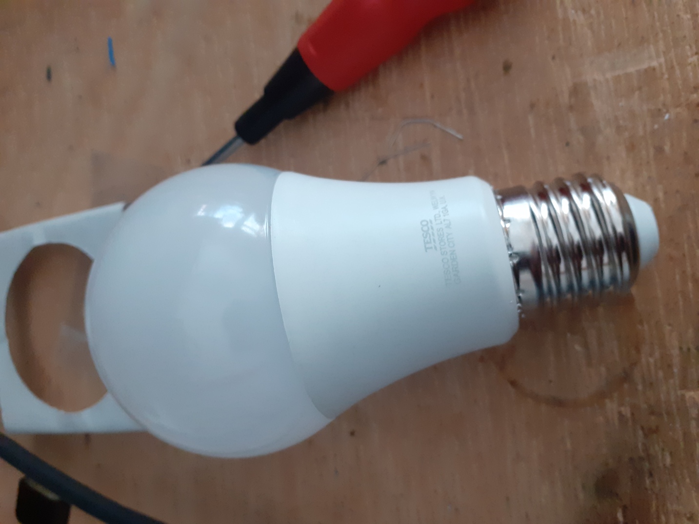
Everyone needs a bedside lamp! Besides, my fiancée had been known to have difficulty waking up and falling asleep (a not unencounterable problem in a world of perennial light pollution, mobile phones and early-rising hammer-drill operators). And anyhow, I needed an excuse to make another. I started as before:
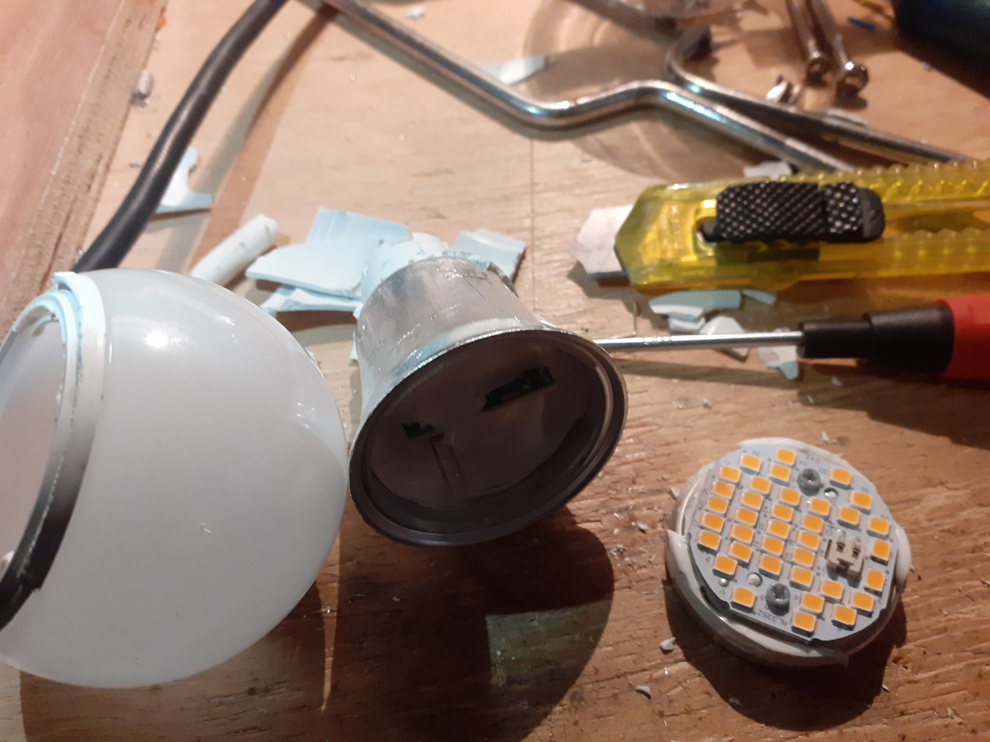
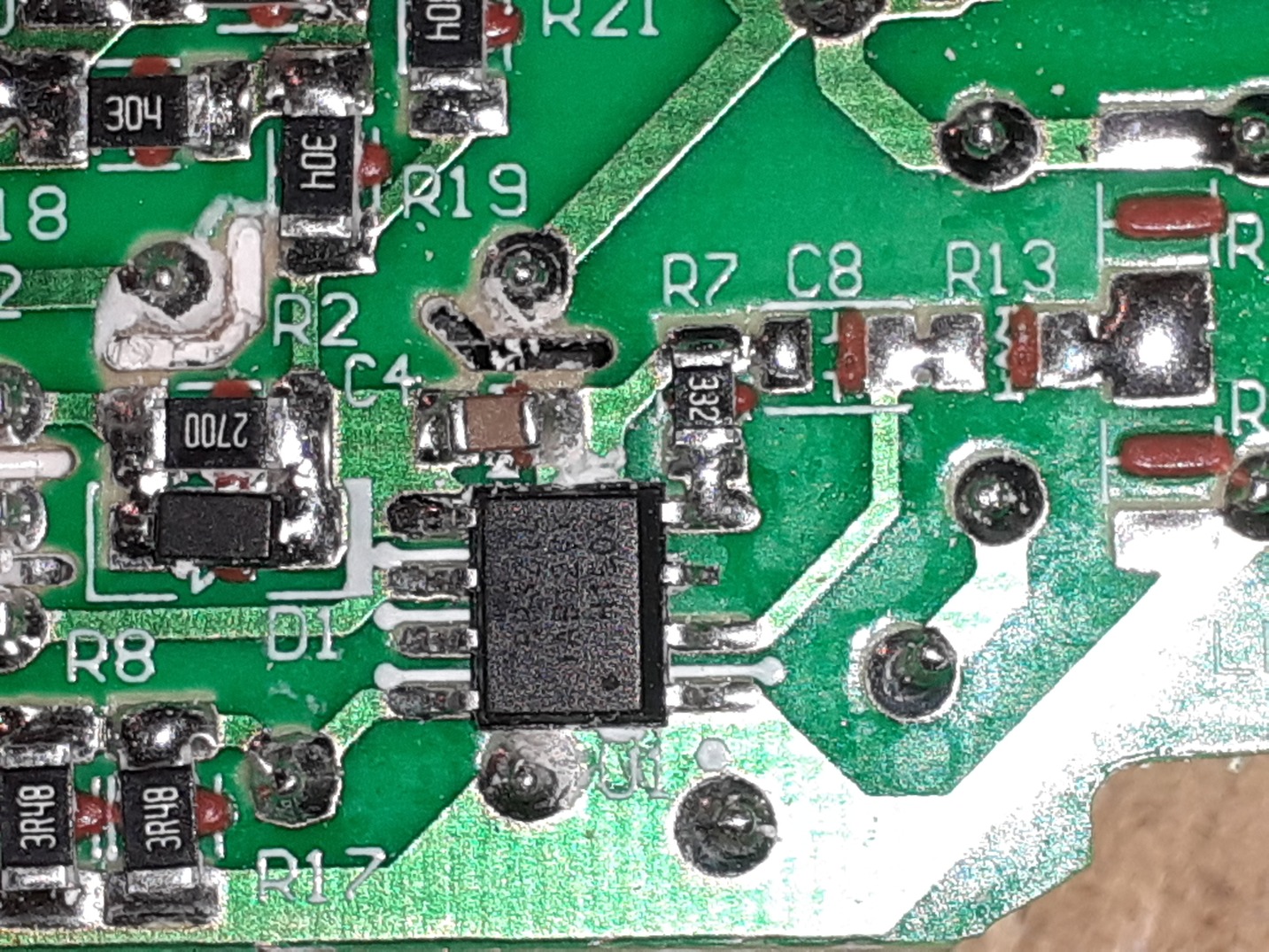
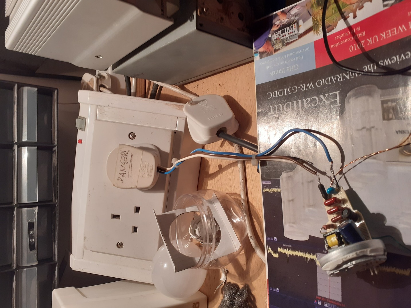
This time it’s a bigger bulb, with a full flyback psu. This complicated PWM feedback: I can’t remember quite how but it was possible to get a degree of fading, but hardly down to nothing:
At this point I very thoroughly blew the whole thing up. I do not quite recall how—and it was rather late at night—but I suspect I forgot the PSU had no isolation in it and connected an oscilloscope probe ground to something I shouldn’t have. I had been intending to try PWM with a mosfet shorting the output (which works by triggering the PSU’s overcurrent protection to shut it down). But that felt like a pretty horrible hack, so it’s perhaps as well I didn’t end up using it.
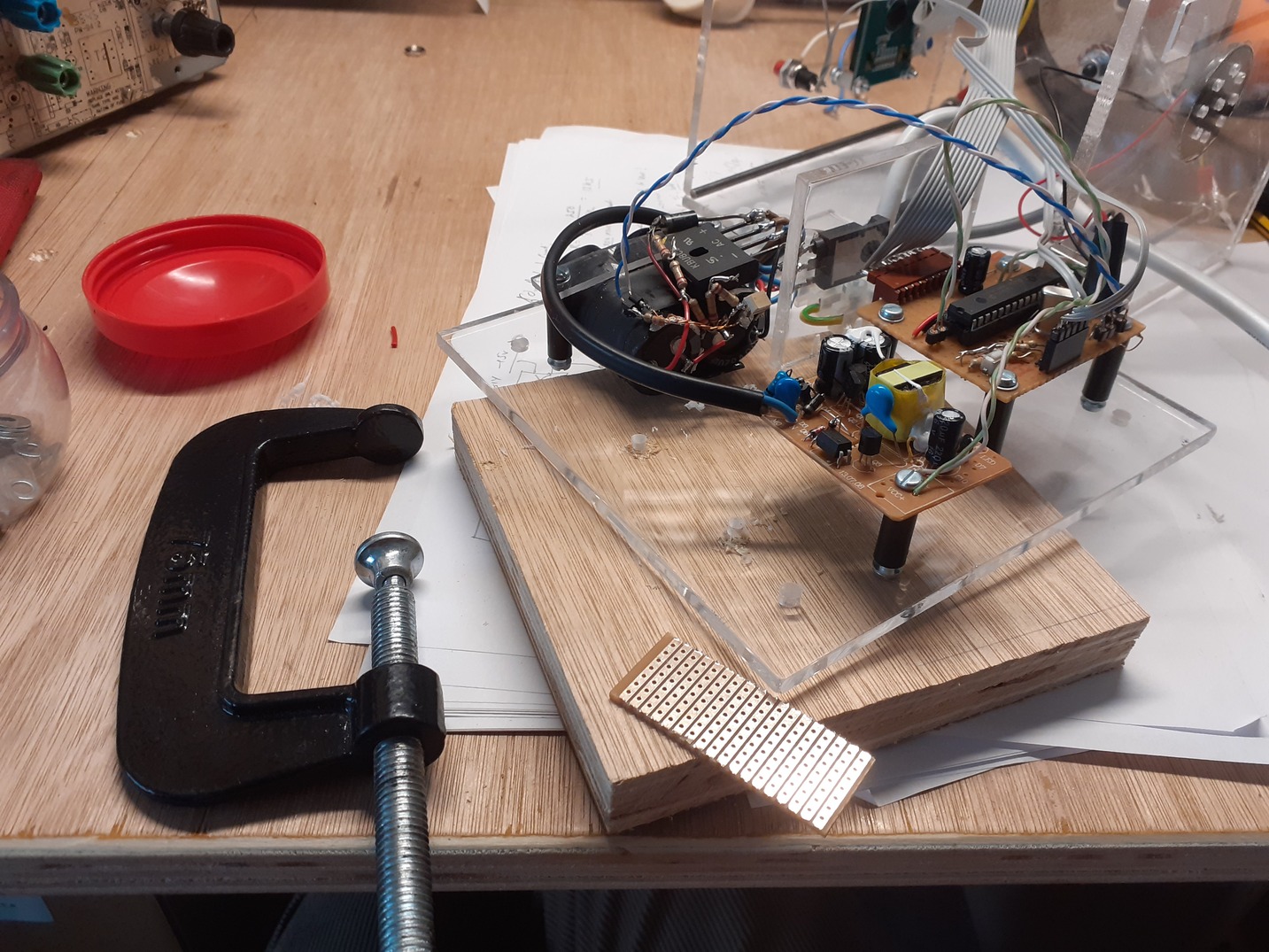
The obvious approach was to do a proper mosfet trailing-edge dimmer and fit a standard lamp socket. But I did not have any paired power mosfets, so I tried a single-mosfet + bridge rectifier solution (the circuit can be found floating all over the internet):
The trouble with this is that one depends upon a large capacitor to supply the mosfet gate voltage, whilst simultaneously shorting out the capacitor. Thus the maximum duty cycle is something like 90%, and the mosfet gets warm from the poor turn off. Thus I moved on to the next version available all over the internet—rectify the mains and chop the resulting dc directly with the mosfet, using a smoothed HV + resistor + optoisolator to feed the base. For faster turn on/off we can invert things and have the optoisolator pull the gate down (since continuous gate current is very low) via a PNP transistor. I followed the internet in putting the capacitors on the HV side to avoid having to think about charging constants, but the only capacitors available were rated at 200v, so two were used in series. (I think these capacitors came from an old set top box.)
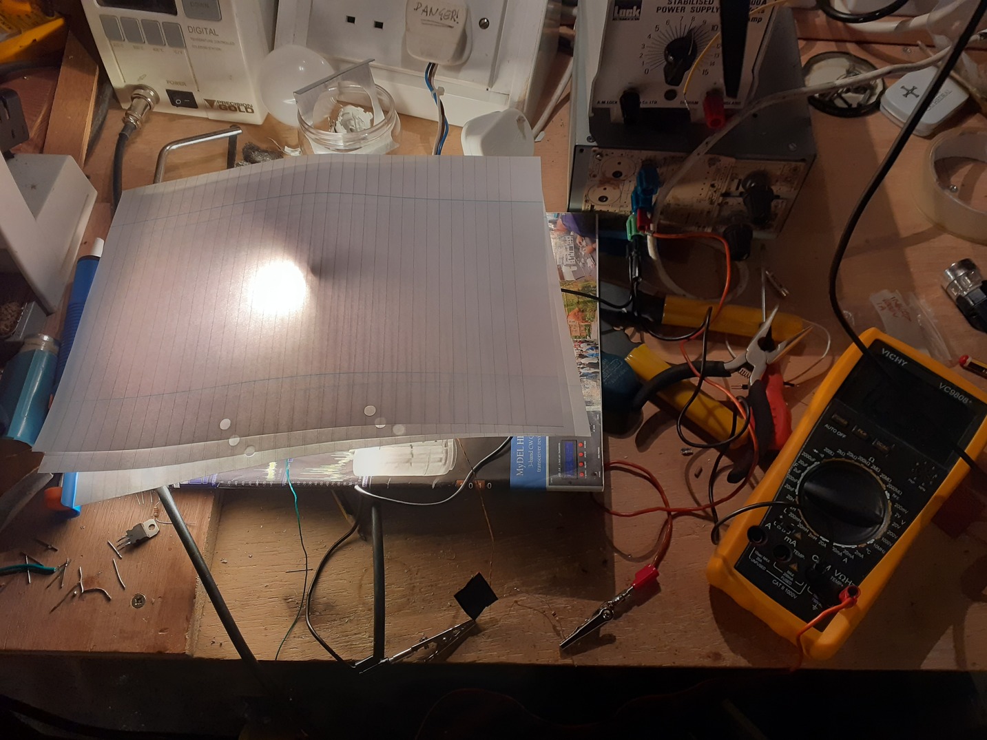
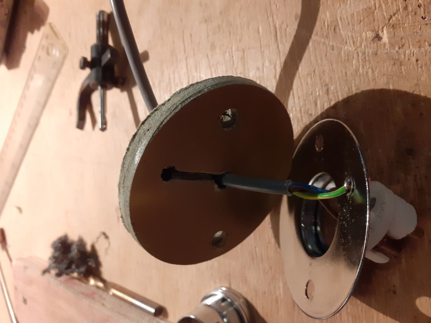
By this point I’d worked out the overall style, and the lamp fitting had arrived. Here it is mounted on some laminate for heat insulation reasons:
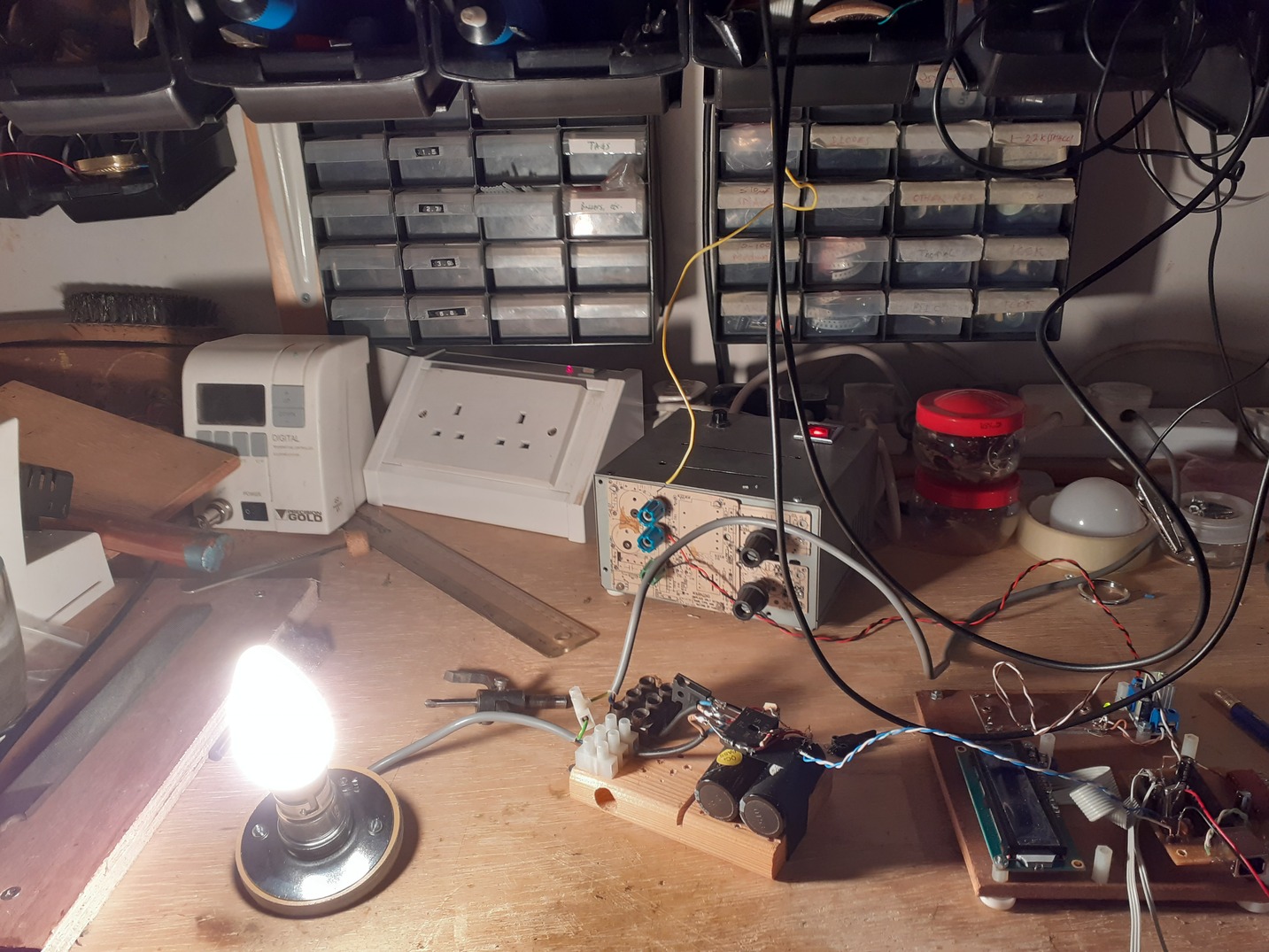
and a test with this junkbox DC fader could be done:
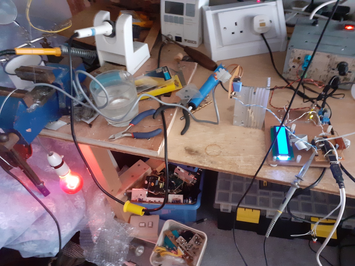
The hardware is the same as before—a PIC18F2550, HD44780 compatible 16x2 lcd,
some buttons, etc, and a 5v psu pulled from some charger or other. The code is
a horrible mess. It’s online at
2e0byo/sunrise_clock. It began life
as a Pinguino project, but I quickly got fed up with working in a half-baked
IDE. Pinguino is fake c++ which transpiles to C and then compiles with the
standard (albeit not very standards-compliant) Microchip toolchain. So I pulled
the transpiled files from the build dir and started hacking them directly.
After a lot of messing around I had a minimal user.c + libraries which,
together with a main.c which is mostly #ifdefs and enough definitions,
produced binaries which did the right thing. The development from then on is a
horrible mix of high-level convenience functions and direct port setting. A
testsuite would be nice, but it’s too much of a mess to be worth it. However,
the code now provides:
- A multi-level menu with entry functions (and a menu loop handling debouncing, timing out, etc)
- Sunrise alarm with optional (fading on) ringing
- Snoozing
- Sunset
- Adjustable lamp
- Soft actions (all brightness changes are fades) to protect eyes
- Adjustable min/max thresholds
- Persistence (EEPROM) of parameters
- Time display in all modes without visible flickering
- Display writing without flickering, despite doing it backwards (display updates in main loop)
- A basic HAL to allow adapting to multiple different hardware configurations
It would have been much more sensible to have started with the display code and build from there, but this code has been running on 3 different devices (it was backported to the original hardware) for more than a year now, and I think all the bugs have since been ironed out.
Case
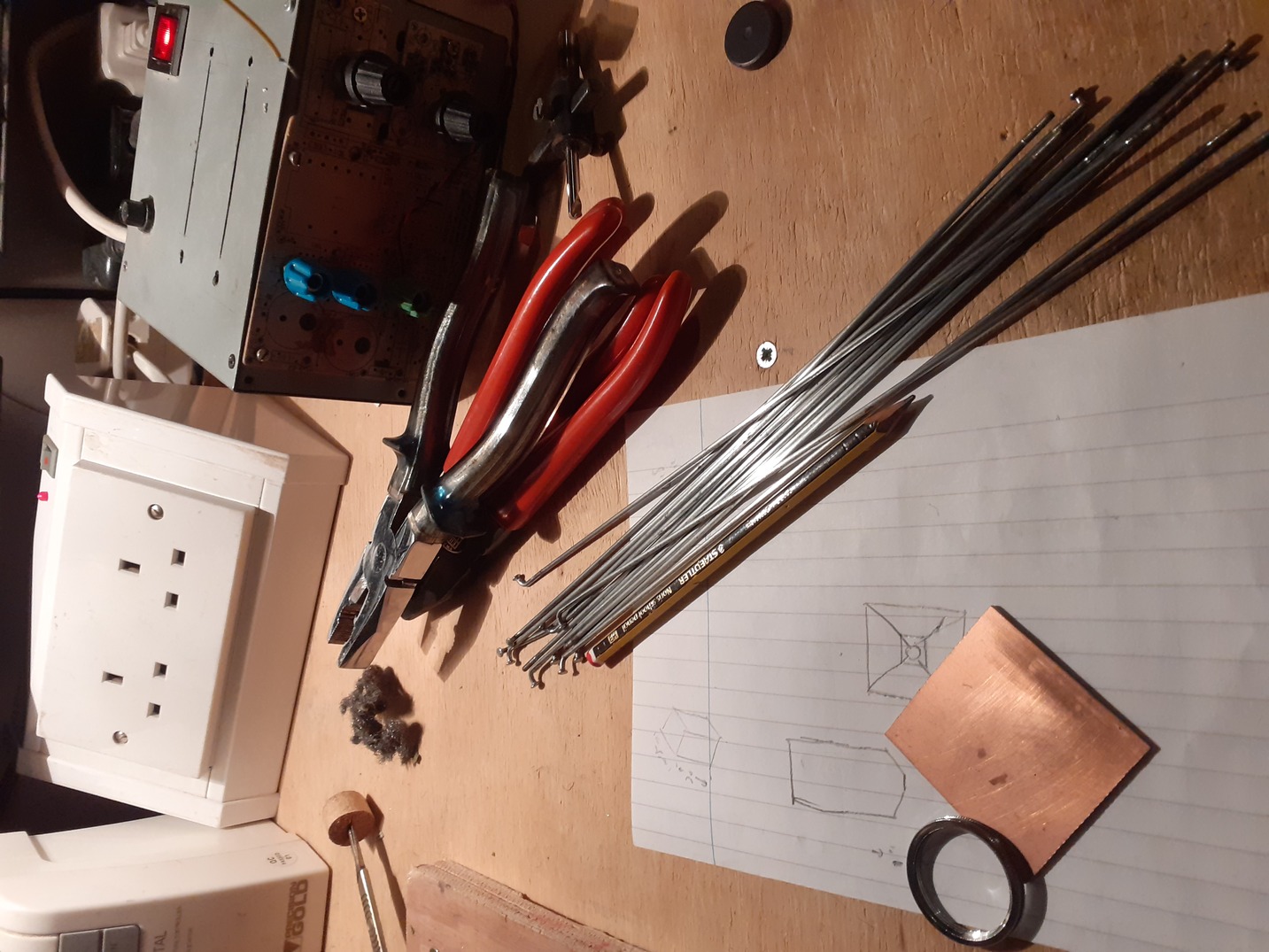
The lampshade has a frame from old bicycle spokes:
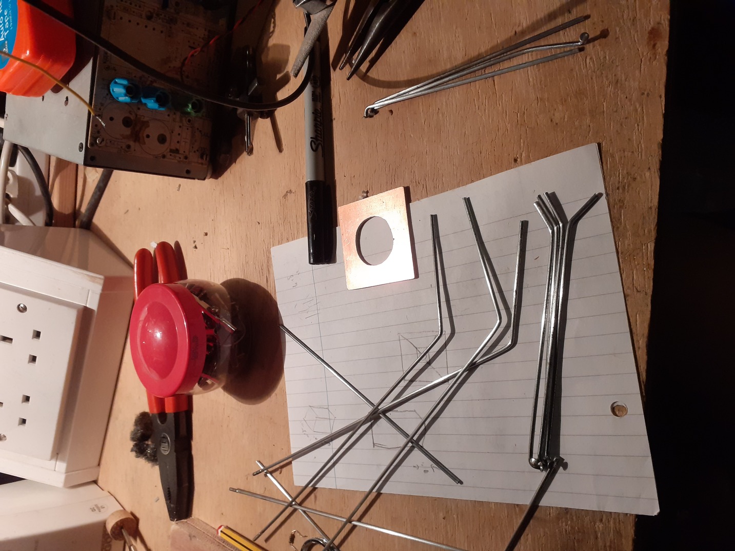
Which bend neatly and remain straight:
And were then soldered together with the gas iron (a nasty fiddly process of which there are no photos) and covered in paper.
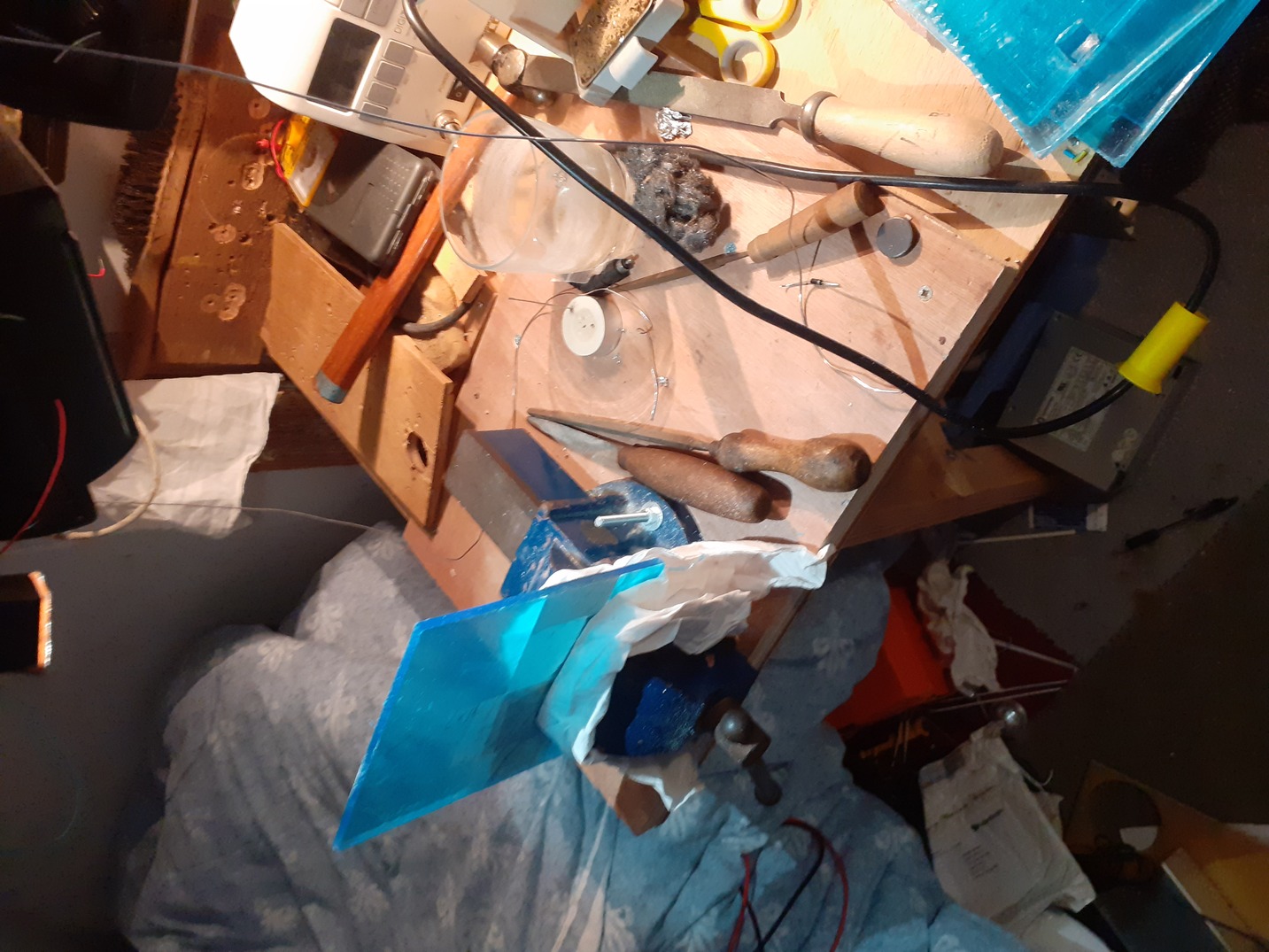
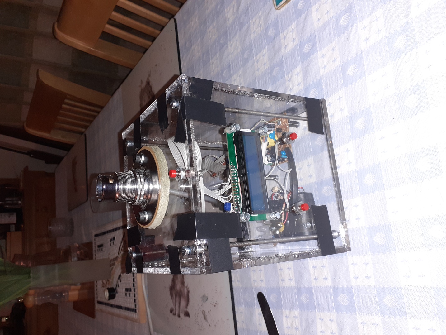
The case is a basic clear perspex box. I ordered the plastic pre-cut:
drilled, cut and draw-filed it:
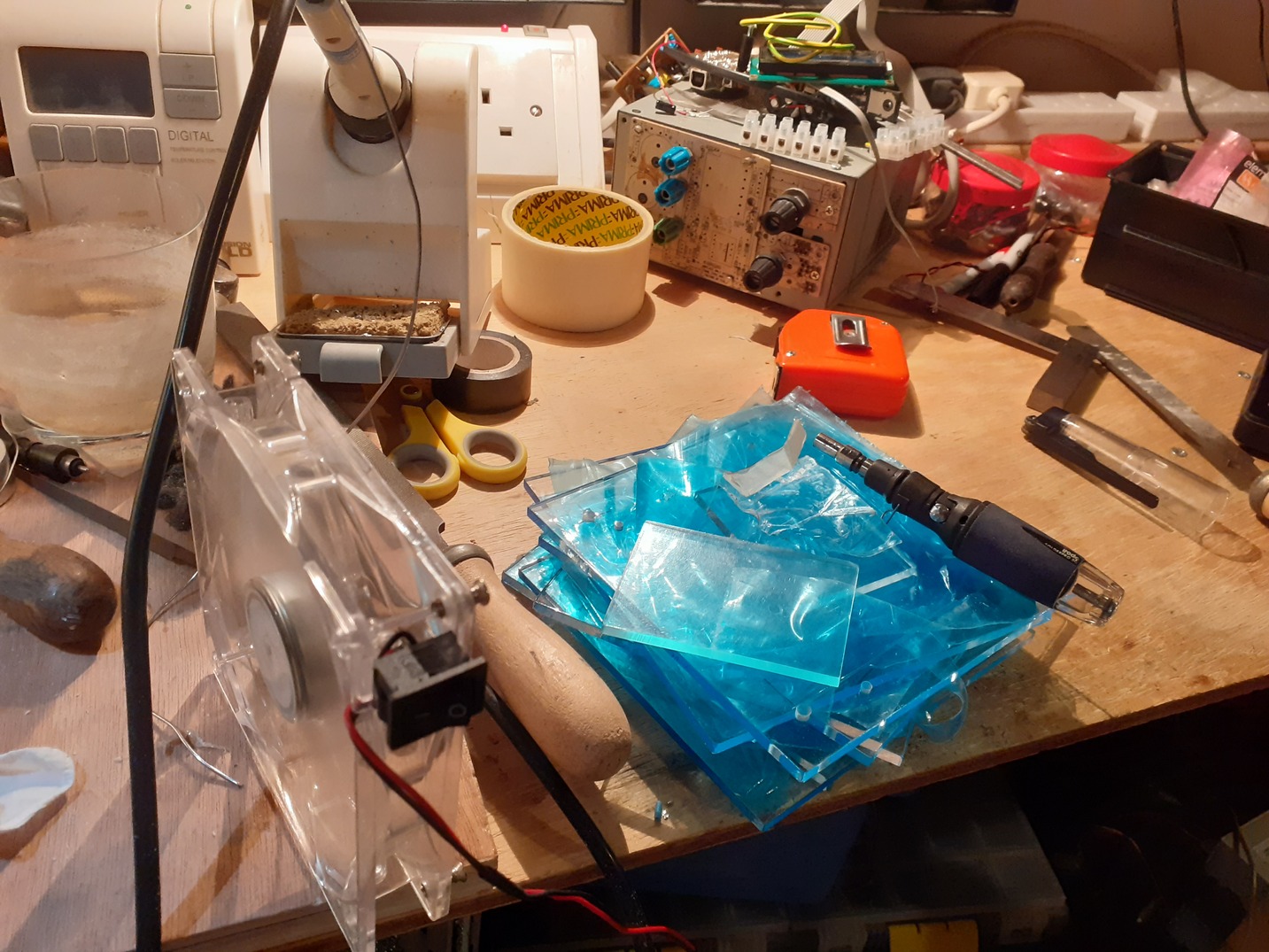
flame polished:
And glued the whole thing up (meanwhile the lamp shade was undergoing heat testing to make sure it didn’t catch fire):
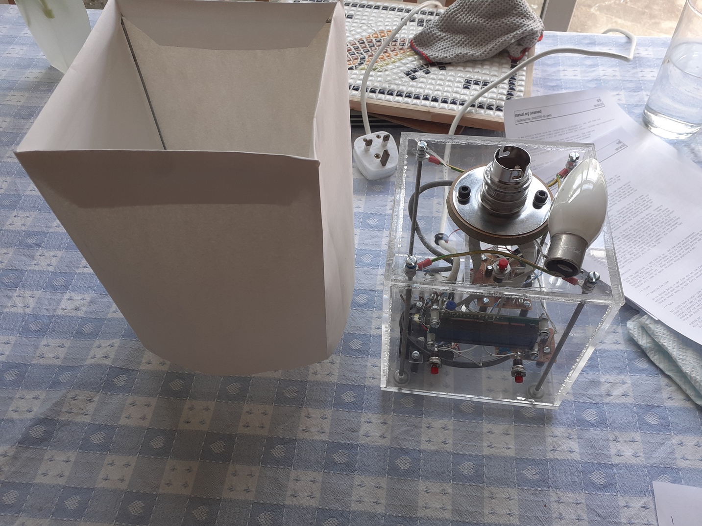
And then installed everything. Sadly I overtightened one of the support rods and started a crack. It’s pretty tiny in these pictures, but it has grown with time (of course) and I should really replace the top piece.
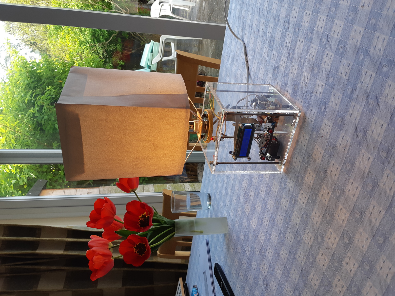
All together it looked very good:
Mains Tick
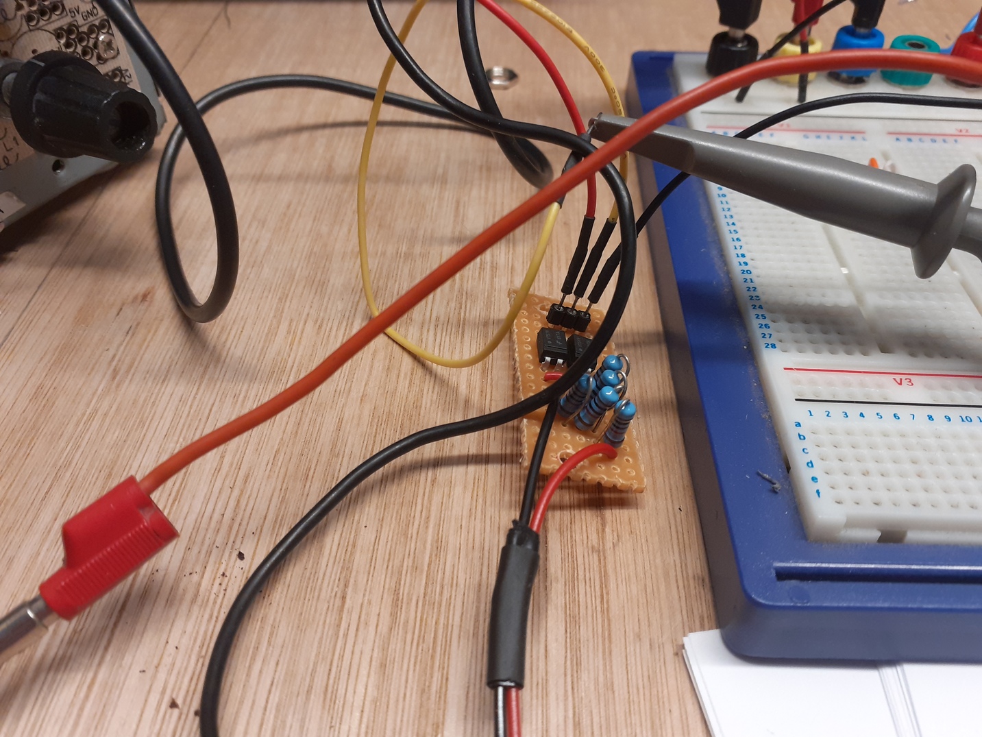
At this point the clock used the same software RTC as before. The drift was tolerable but annoying. A much better idea would be to take the tick from the mains: long-term mains frequency stability is excellent (better certainly than uncalibrated 32.768kHz crystals with no sort of temperature compensation). Thus later I added a pair of back-to-back optoisolators as a TTL switch, fed via 5 series 10K resistors to supply the specified switching current. (In point of fact these resistors get rather hot, and one could likely get away with a much lower current. But I have a lot of 10K resistors.)
In use it squeezes on one side of the HV side of the base of the lamp.
Since installation the clock has been rock-solid: only the ntp controlled devices in the house are better. The only trouble is that, now we are married, the lamp wakes my wife up a good deal before it wakes me up (naturally, it is on her side of the bed). Thus I should really make another clock. Although in that case they should synchronise brightness, and that would really require rewriting the code for a better SoC with integrated bluetooth….
