Now that we have a working counter and display the next thing to look at is the timebase. The timebase I built when first working on this counter is odd. It uses, for some reason, a 3.2768MHz crystal divided by (2^16 * 10n) to get a gate pulse which is a multiple of 1s, then further divided and decoded by a 3-to-8 decoder to generate pulses which latch the counter onto the display, and reset the counters. This much was copied from EMRFD but without the intelligence that excellent book expects: obviously, this solution is fine for a quick gate but highly tedious for the long gates I decided to add, as well as being useless for pulse-width-counting, which I wanted to make it do like G0UPL’s counter—the other project I copied rather blindly. I’d be much better off with a 10 or 20MHz crystal and drop the needless 2^16 counter. But more on that later when I finish it.
After wiring and rewiring, and wiring in circles, we have a switchable timbase, using real hcmos logic, and a gate, using improvised diode logic (more ICs in the post). This involved one of those multipole-rotary switches. I have a few, and none of them make sense. So I took the case off: it seems this is a three-pole four-throw device, but with the the contacts all so oxidsed most don’t conduct. I cleaned them off:
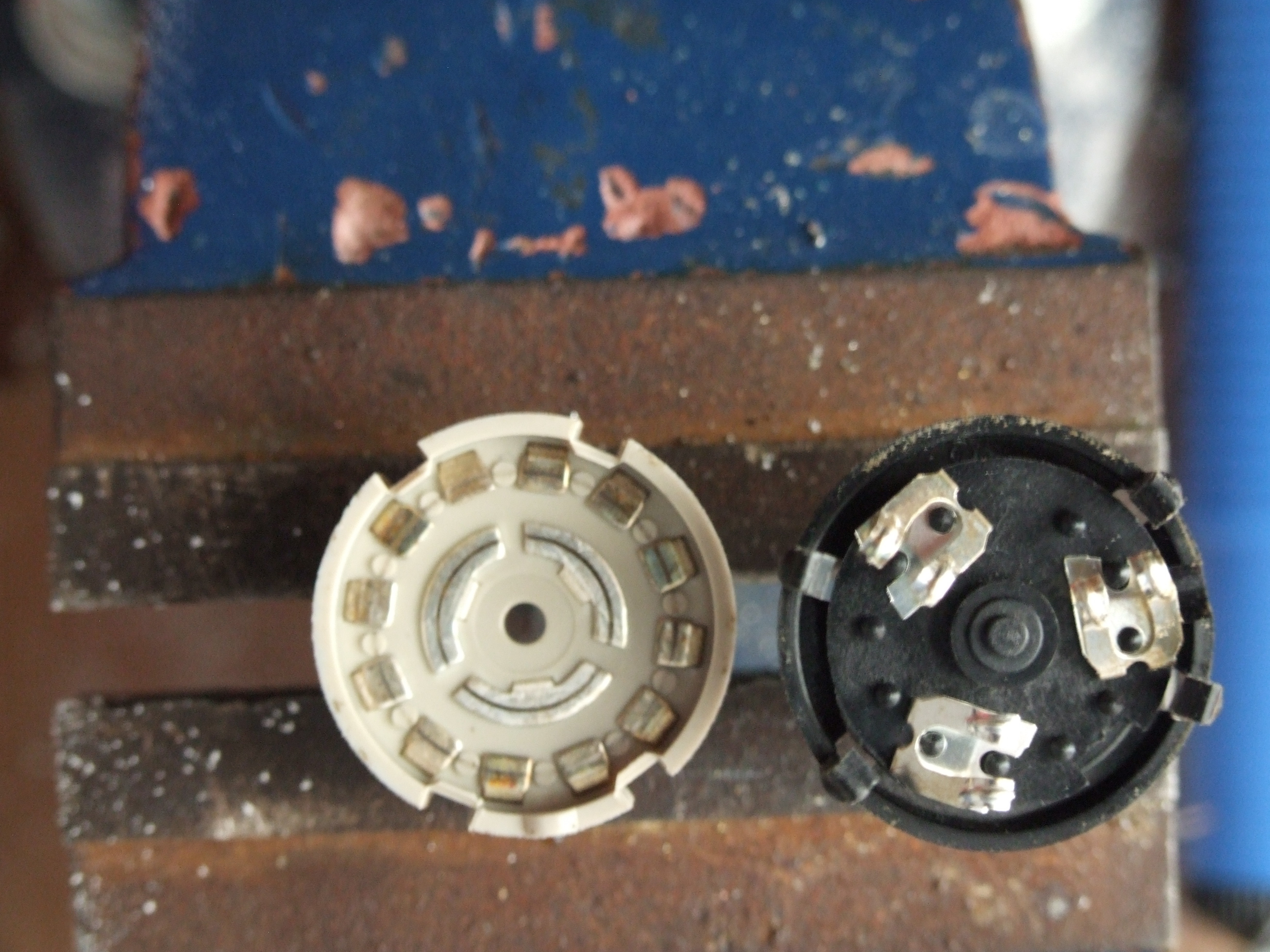
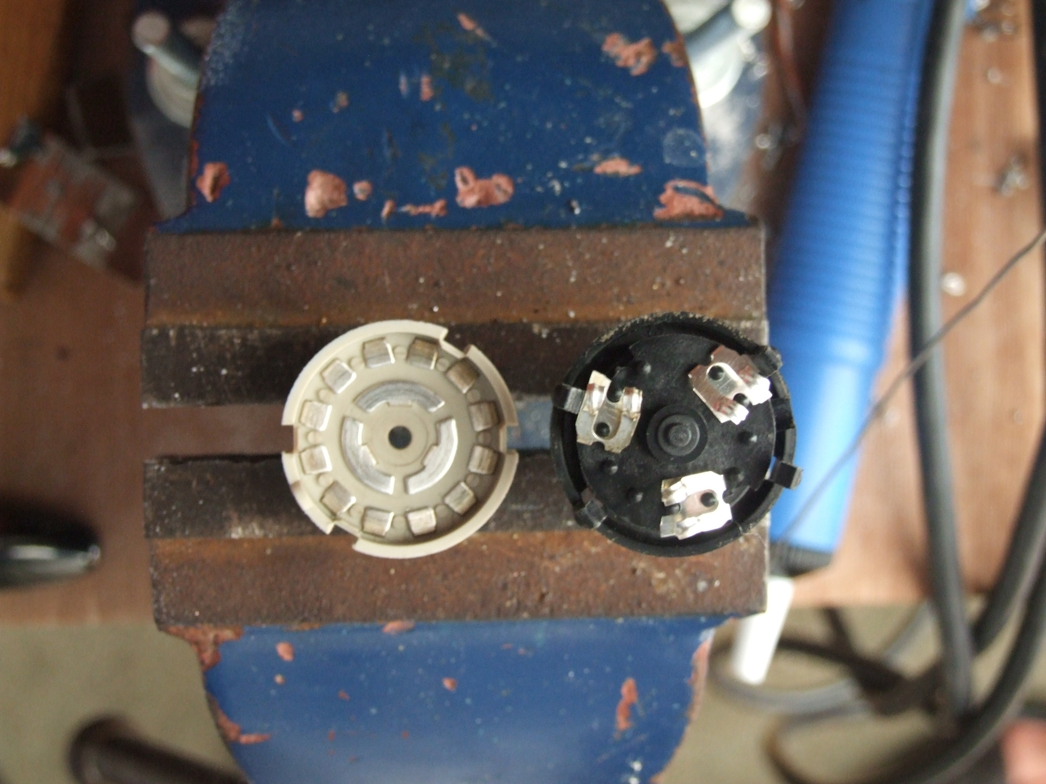
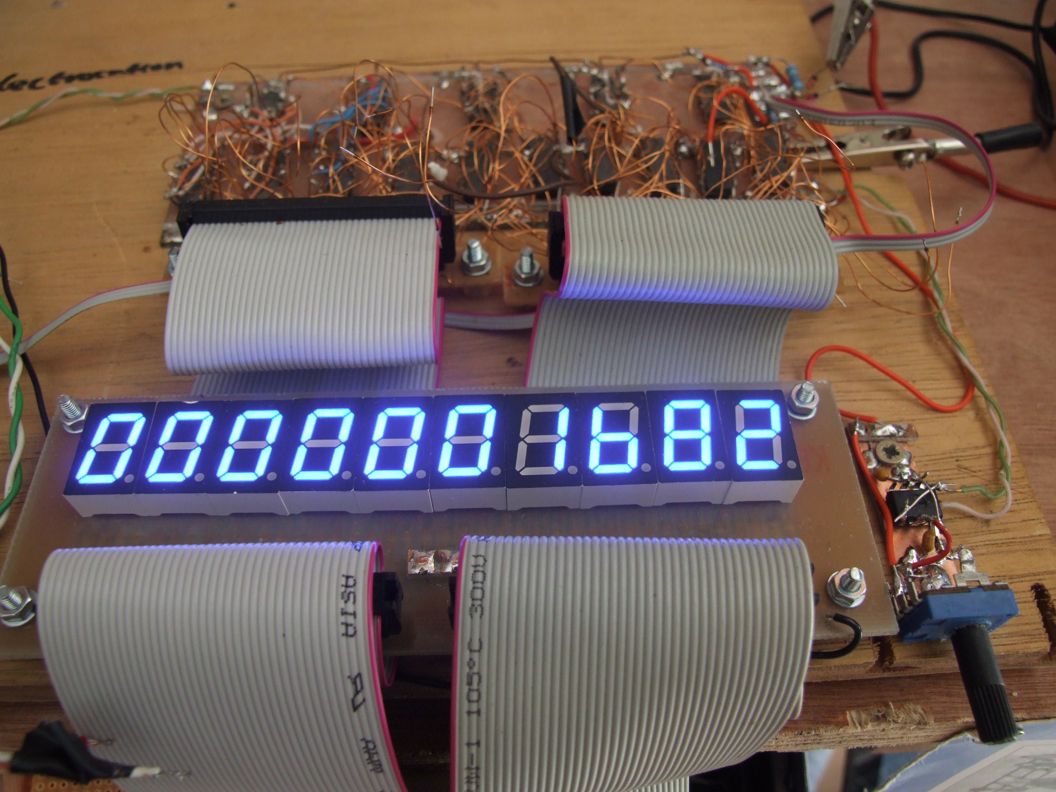
And then took out two of the sliders. Now if we connect the three poles together we have a twelve-way one-pole switch, which is much more useful here. I also removed the completely unneccasery third connection to the hc138 3-to-8 decoder, as two inputs produces 2^2 = 4 outputs, which for 3 pulses is fine. Then we need RTL as the 138 is an active-low device, but the reset and gate pulses are active-high. Connect it all together and we can count our own timebase:
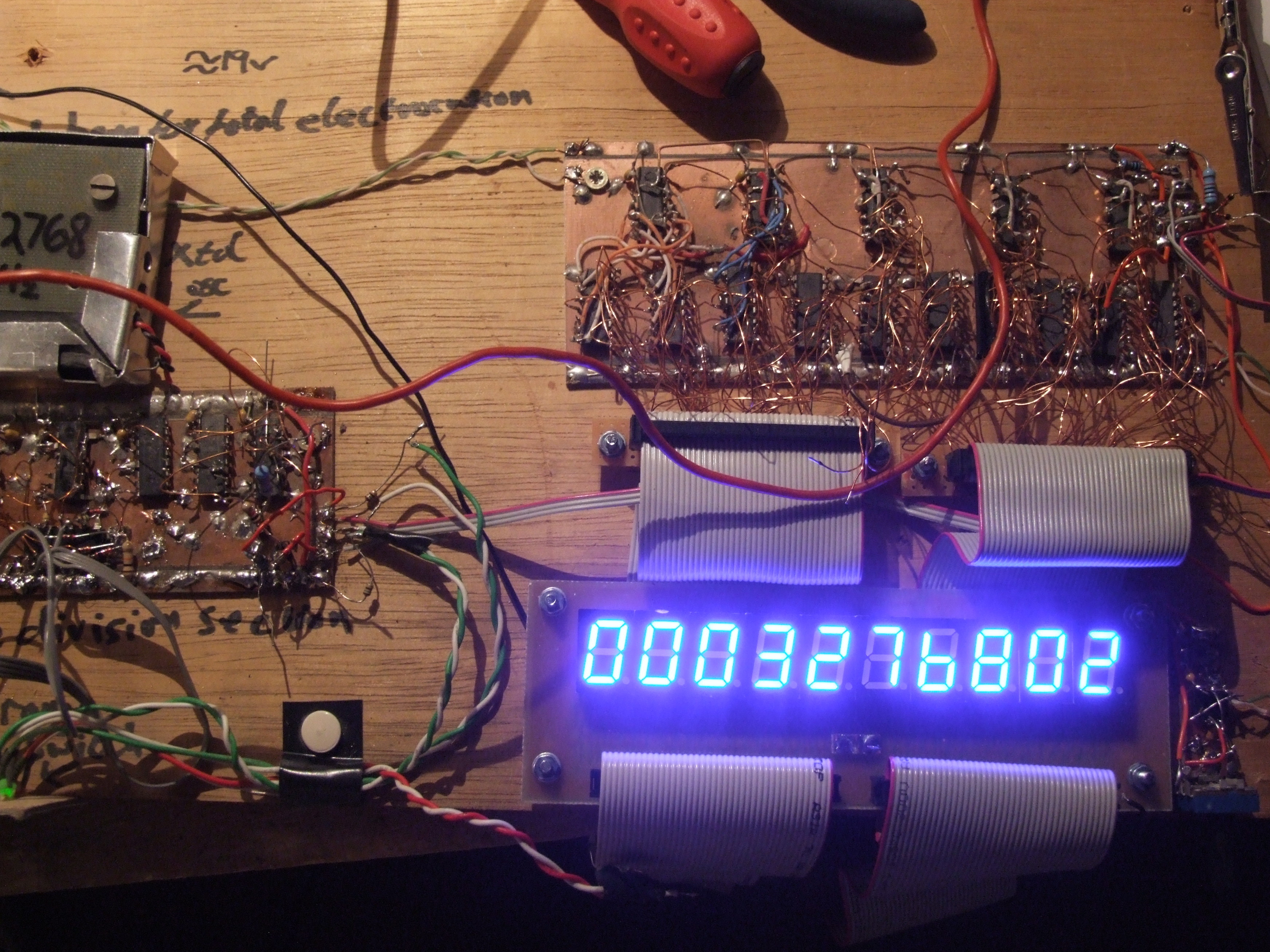
Now what is that last digit about? Surely, unless it drifts .2Hz (this is actually timebase/10) during the count it should always read 0? But at any rate, it’s clearly working. I didn’t show you any photos when things weren’t. For another project I need to know how fast one of those OpenWRT boards can bit-twiddle. So I toggled a gpio with the shell (just echo ‘1’ or ‘0’ to the pseudo-file):
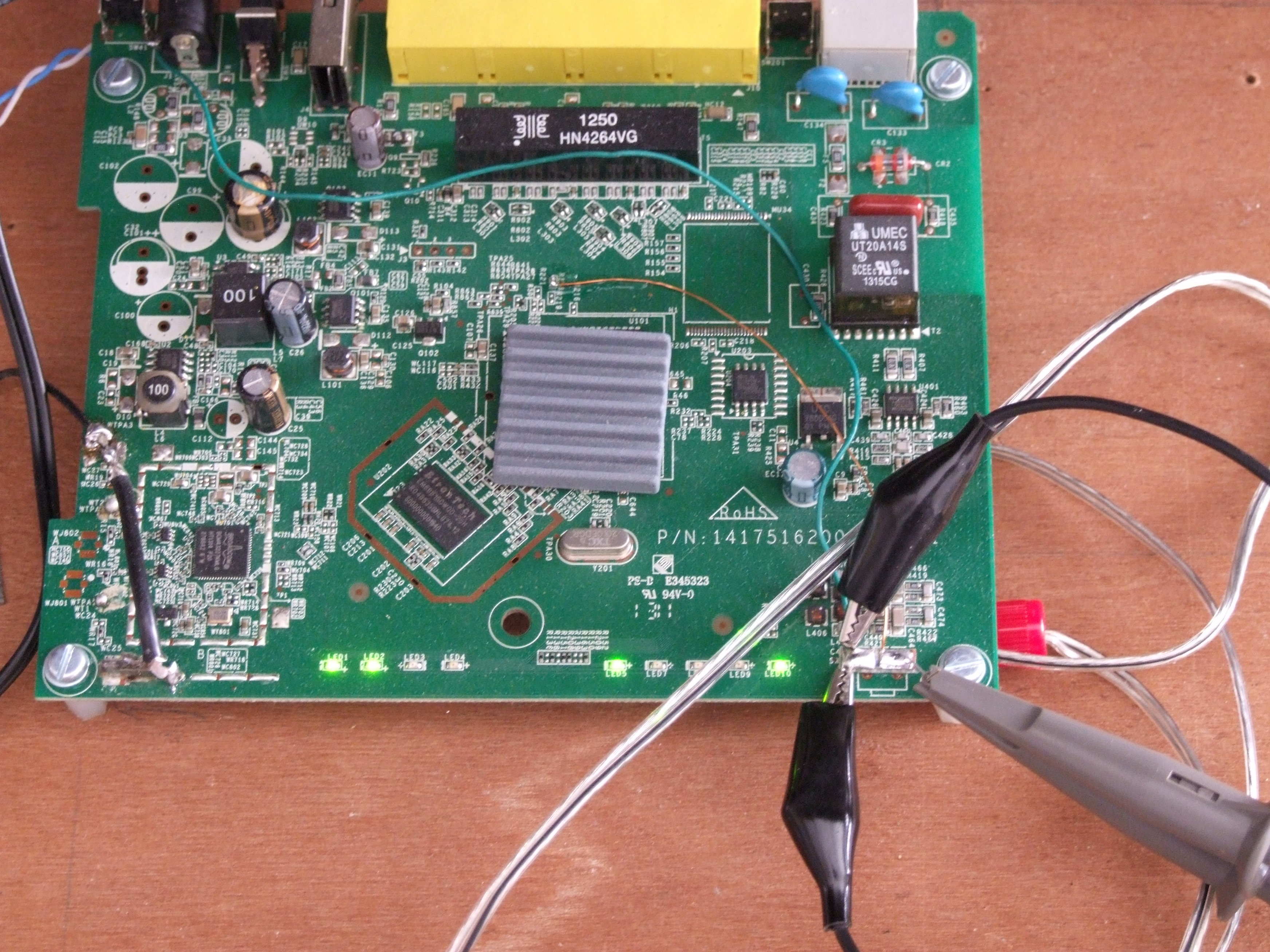
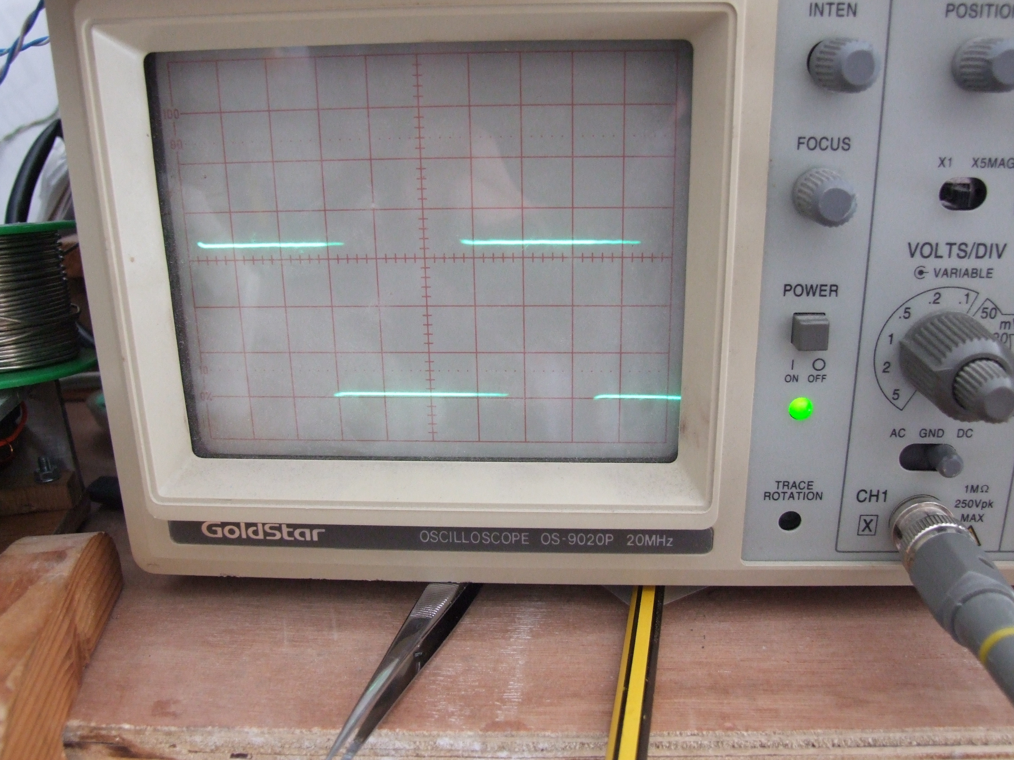
About 1.6KHz. That’s more than quick enough. Here’s another shot with the brightness turned up (the change in value is unrelated, it was not stable!):
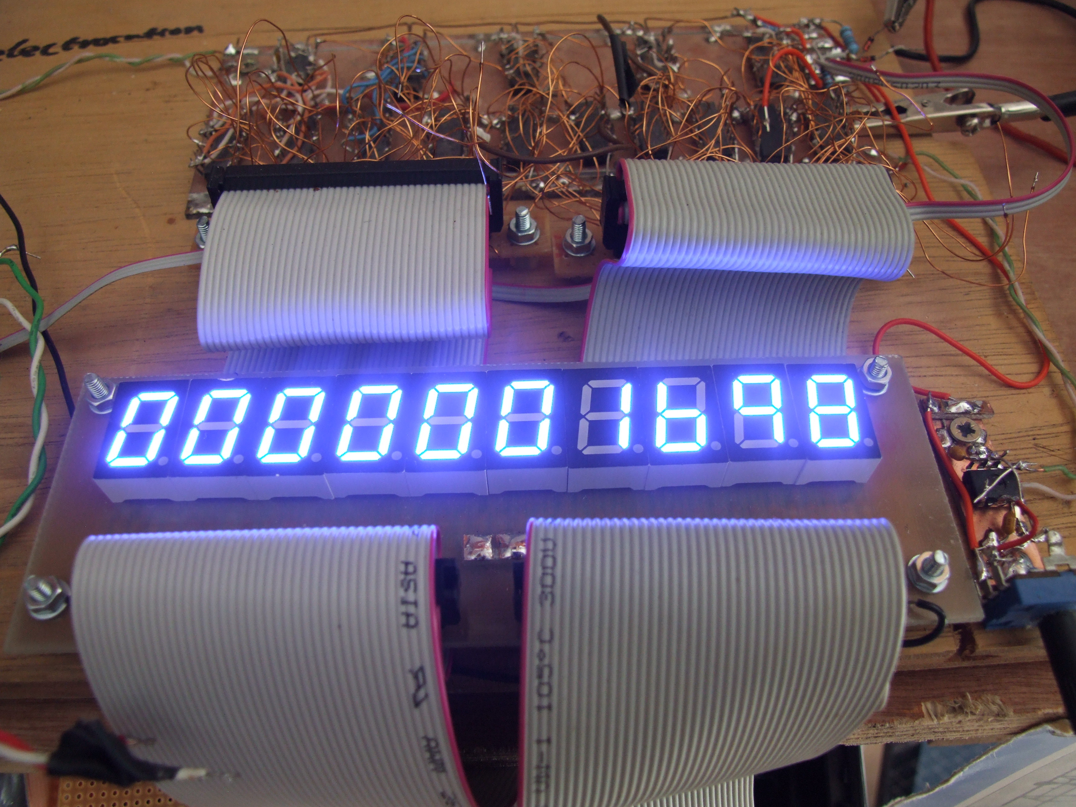
And we have a working (if not at all finished) peice of test equipment. I’ve sorted out the control logic in my head and half on paper, so that will follow shortly when some flip-flops and logic arrive to build it.