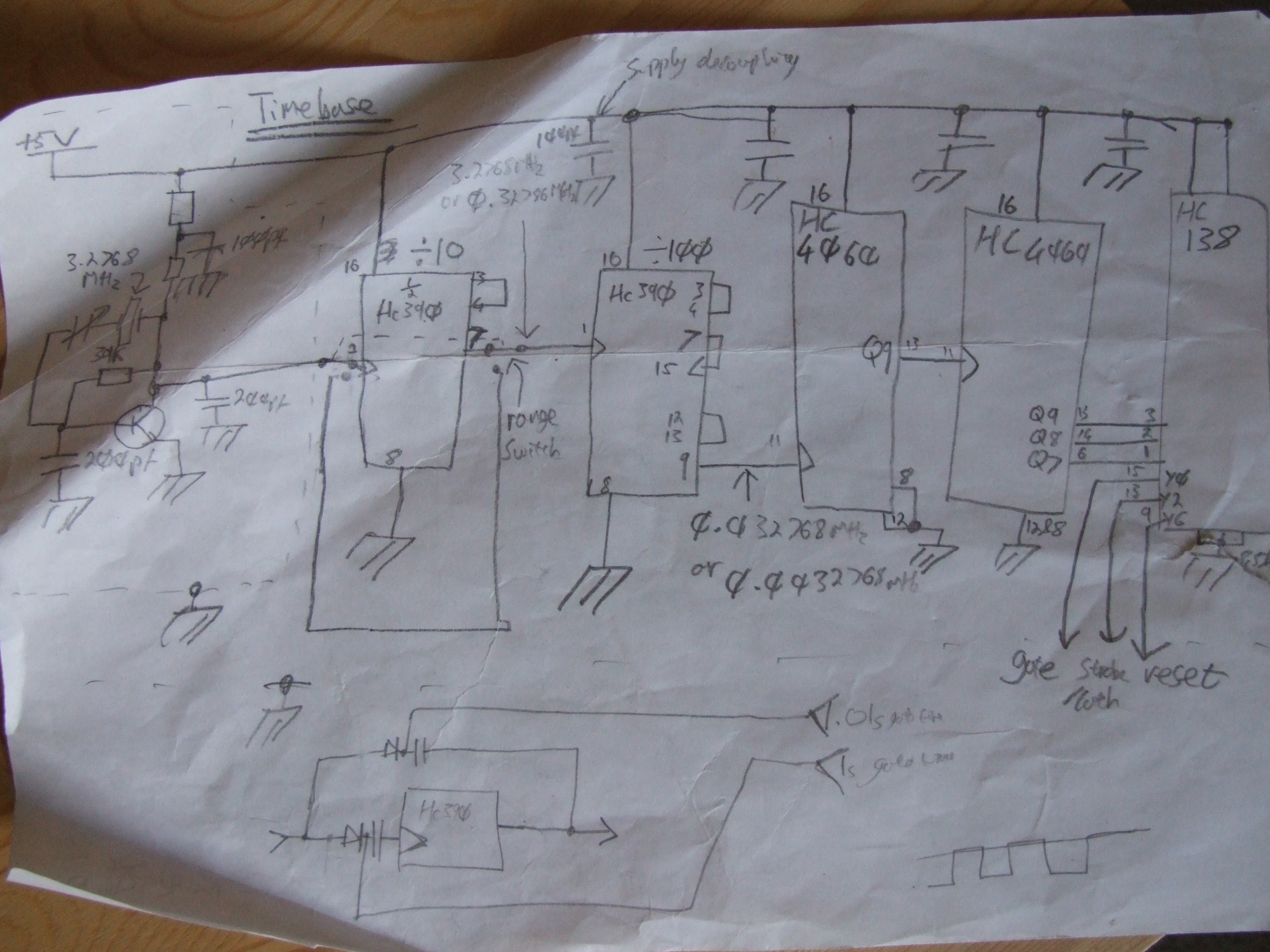
I started this peice of test equipment when I was about 15, I think, built the timebase with enthusiasm, the counting chain with a bit less, and then wondered how on earth I was to attach the 7-segment displays. Surely not one wire each?! So the project languished, and eventually got relegated to the shelf without ever being finished. All I had was the breadboard and two schematics which nearly corresponded with what was in front of me:
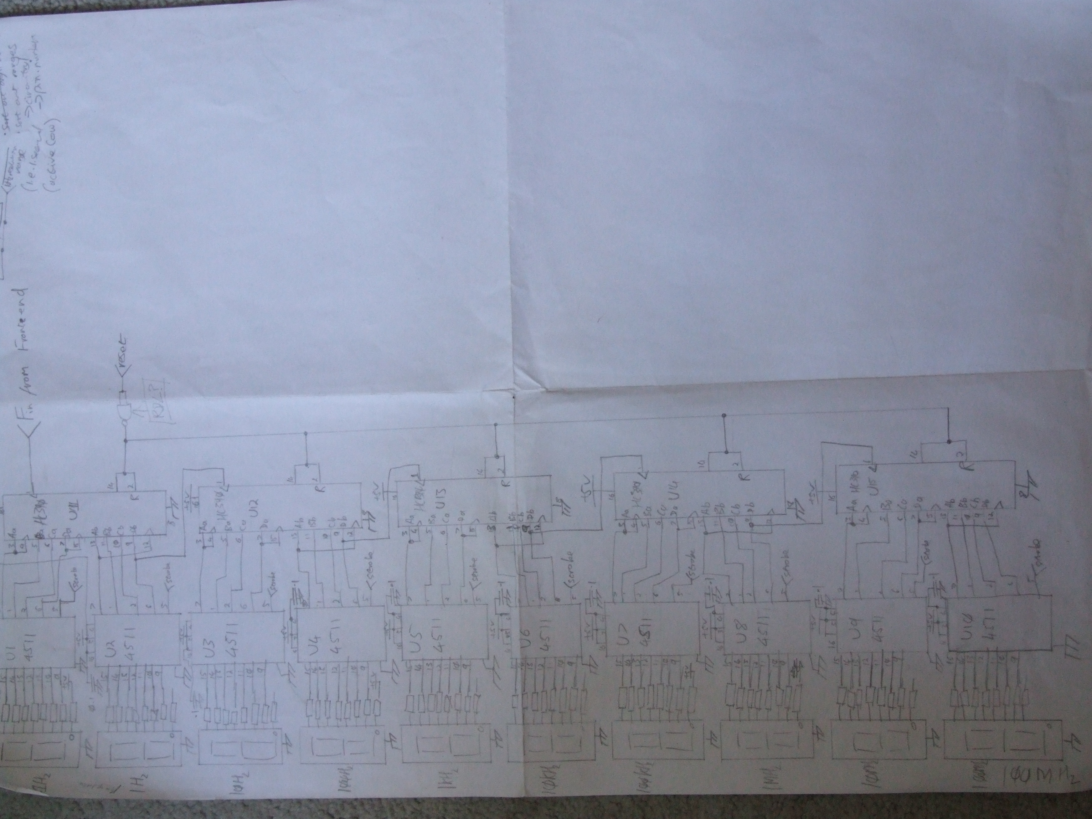
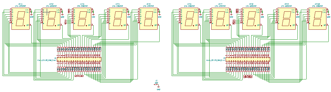
I seem to have started on a more sensible switching scheme, with diode and gates summed at a transistor (might it not be more sensible to use a CMOS Nand gate if we’re going to handle higher frequencies?). Coincidentally I amassed a lot of ATA cables, which have 40 pins. 10 digits with decimal places = 80 leads + ground: could I make a pcb and and use two ATA cables to connect the board to the counting chain? A frequency counter/pulse width measurer would be very useful, and I keep improvising them with MPUs. When I ordered parts for the battery charger (on which more later) I picked up 100 0805 150R resistors. I remembered I’d settled on them to drive the digits, and didn’t re-check the calculation: this was to prove interesting later. Then time to fire up KiCAD and make a very fiddly board:
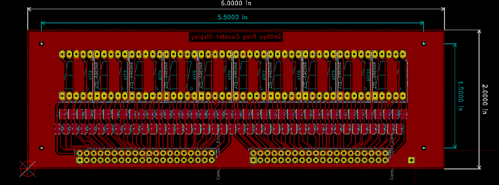
I’m getting the hang of the global tools. Still, I should 1. have set the clearance higher and 2. have used an autorouter, as some of those tracks are dangerously close. In fact, transferring was a complete nightmare—the glossy surface of the paper won’t come off and I had to go around nearly every track with a needle. Next time different paper. Etch and etch and etch, for about 3 hours: the etchant hit saturation quite early. Also need a bigger, and vertical etching tank. Here’s the result:
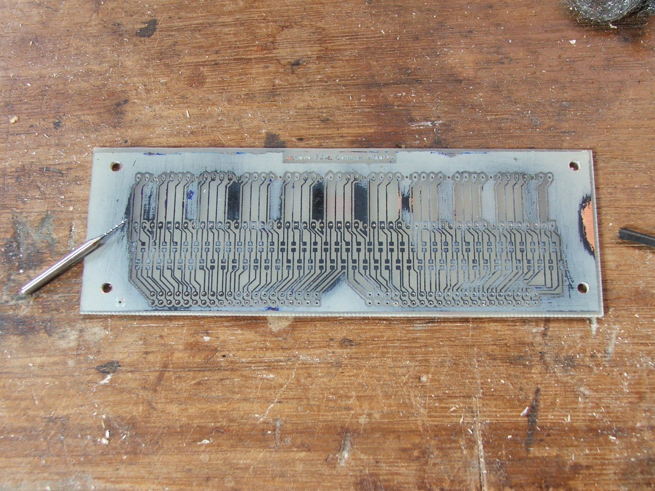
As you can see I left the toner on to guide the drilling, which made things a lot easier. I also drilled the ata header pins at 0.8mm and had to re-drill at 1mm. Then gluing (with a small wire dipped in superglue) and soldering all the resistors, and then the digits and headers:
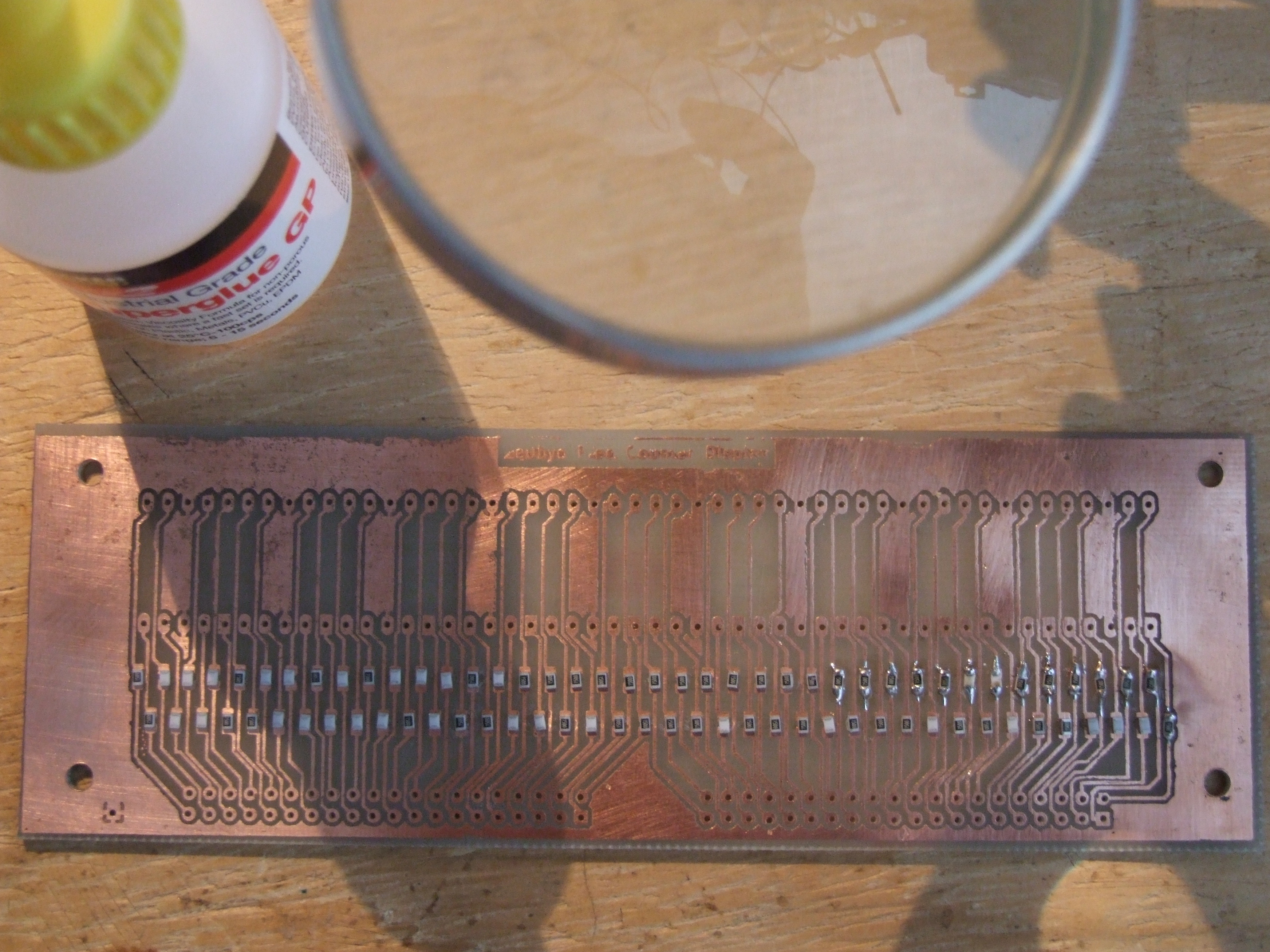
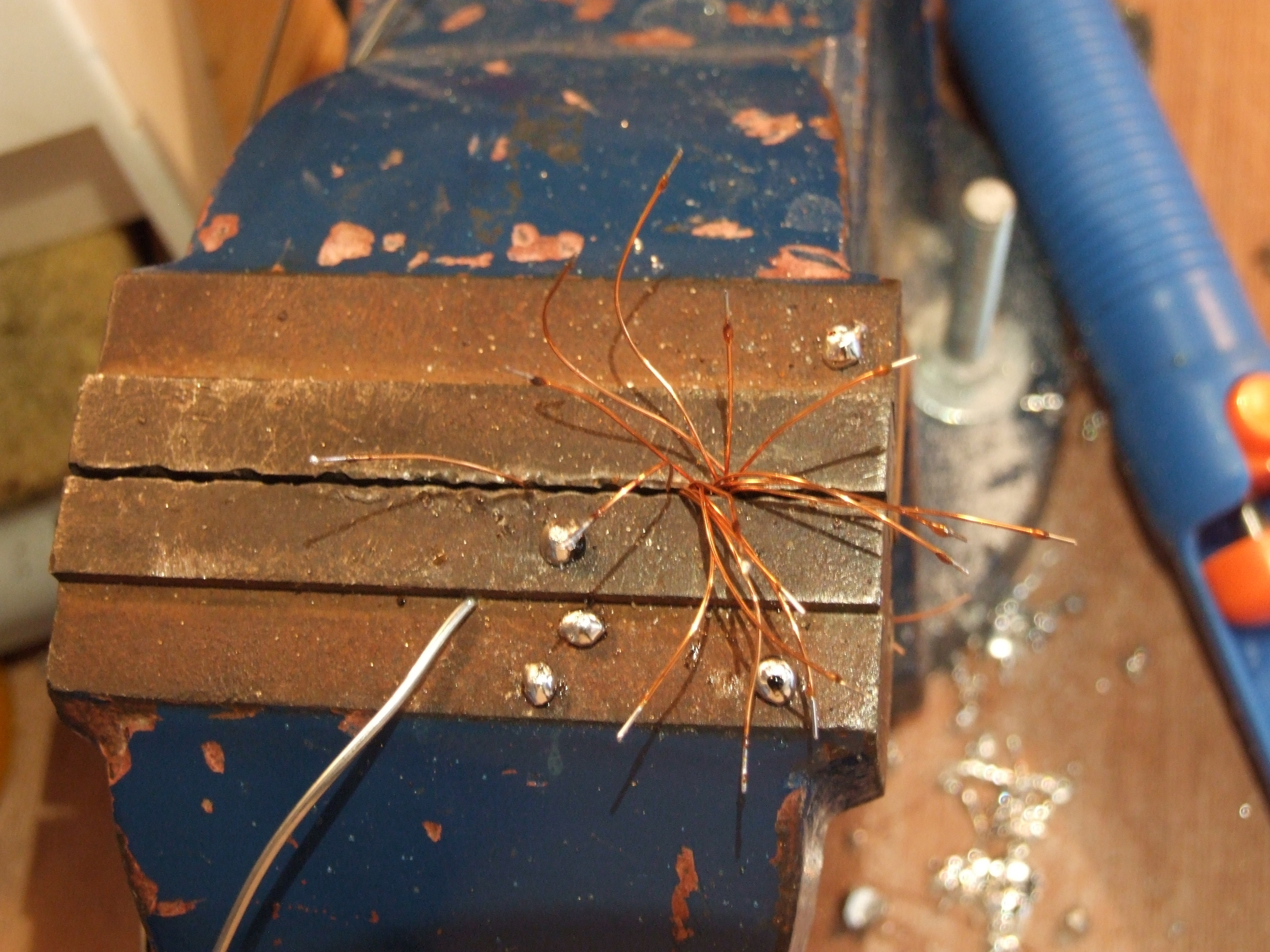
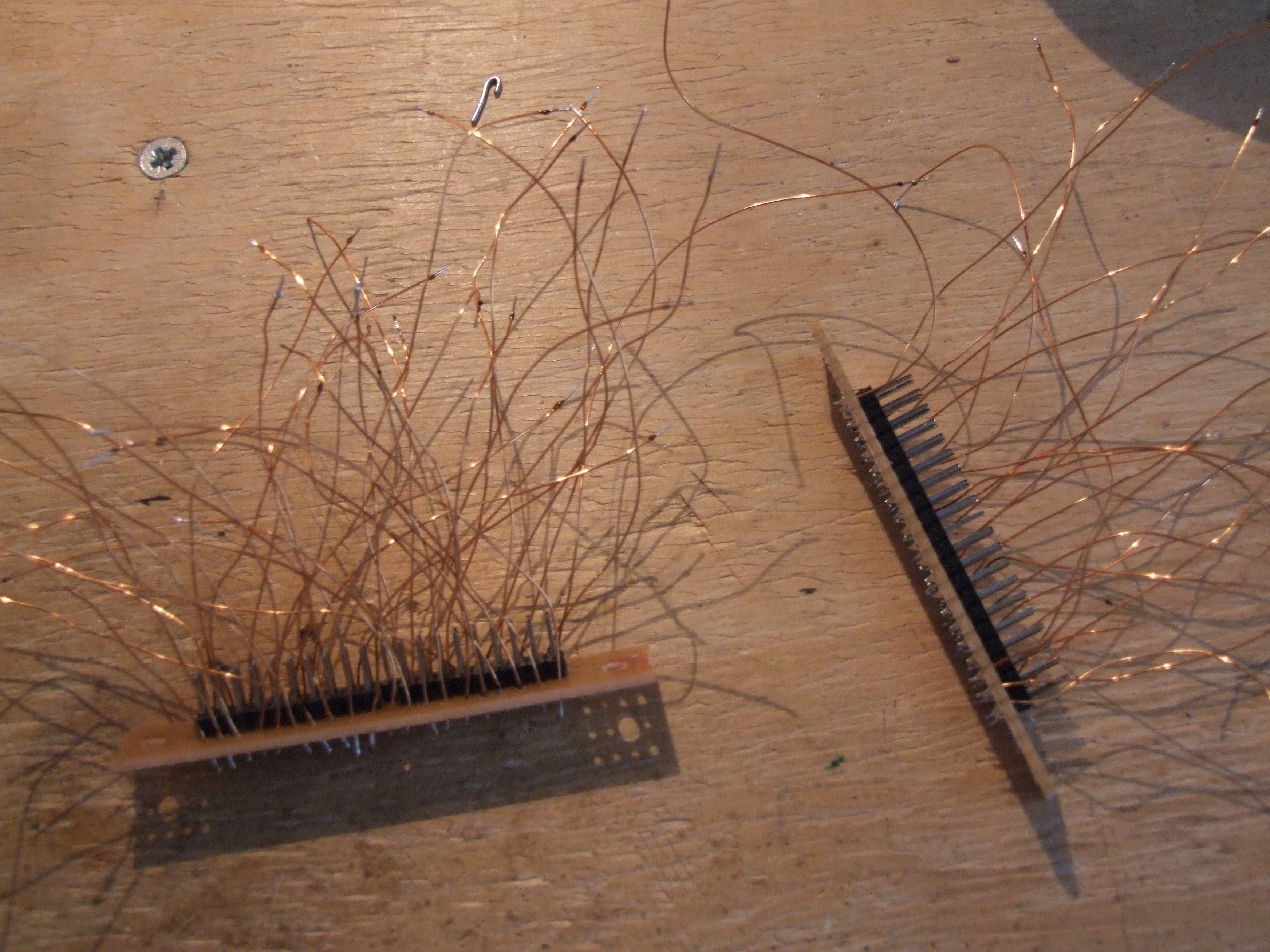
At this point I discovered the ‘key’ pin on an ATA cable which is blanked, and cut the corresponding header pins. Later I found non-keyed cables and had to solder the pins back in place, which was hard work. Now we just need something to wire up the other end with. My preference is magnet wire: I have lots of it, it’s easily stripped with the iron at ~380 but the odd brush with an iron at 290 (soldering temperature) will do it no harm, unlike plastic-sheathed cable which will instantly fuse. So I had to cut and ‘strip’ 80 little bits of wire, which was tedious, and then solder them onto some stripboard along with the headers:
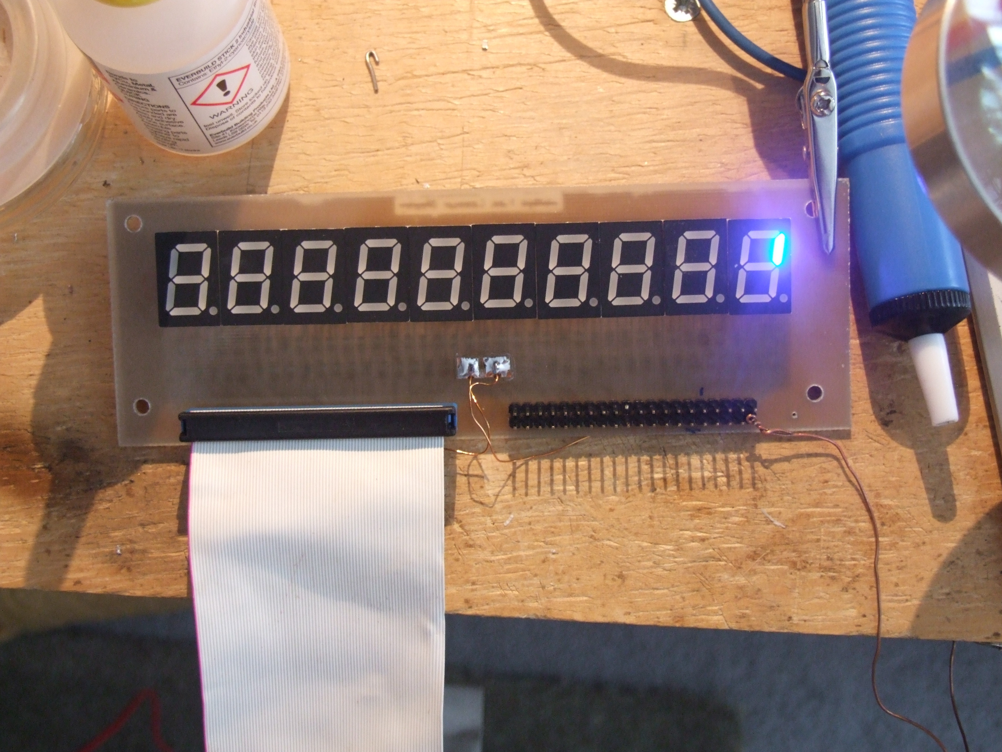
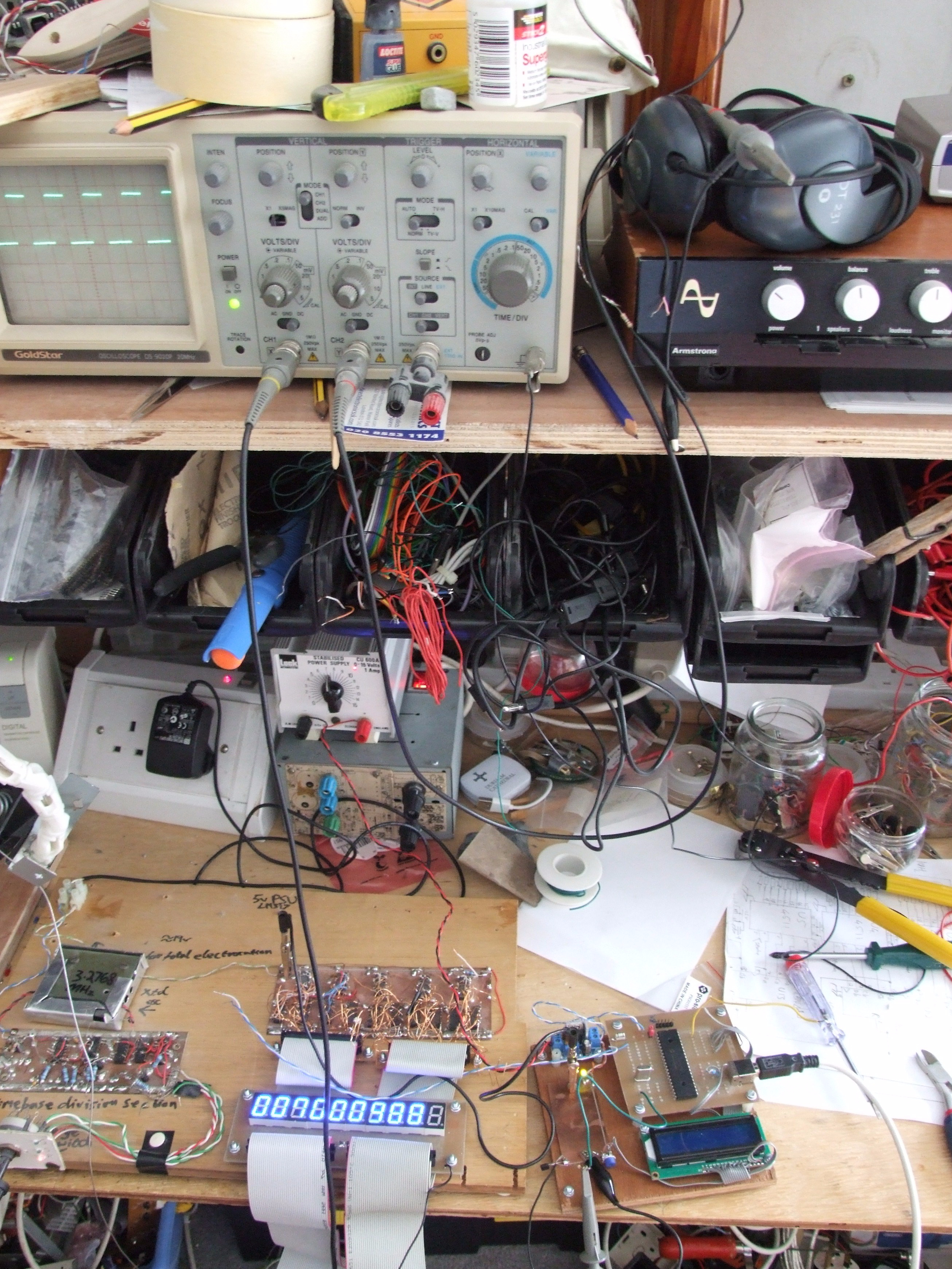
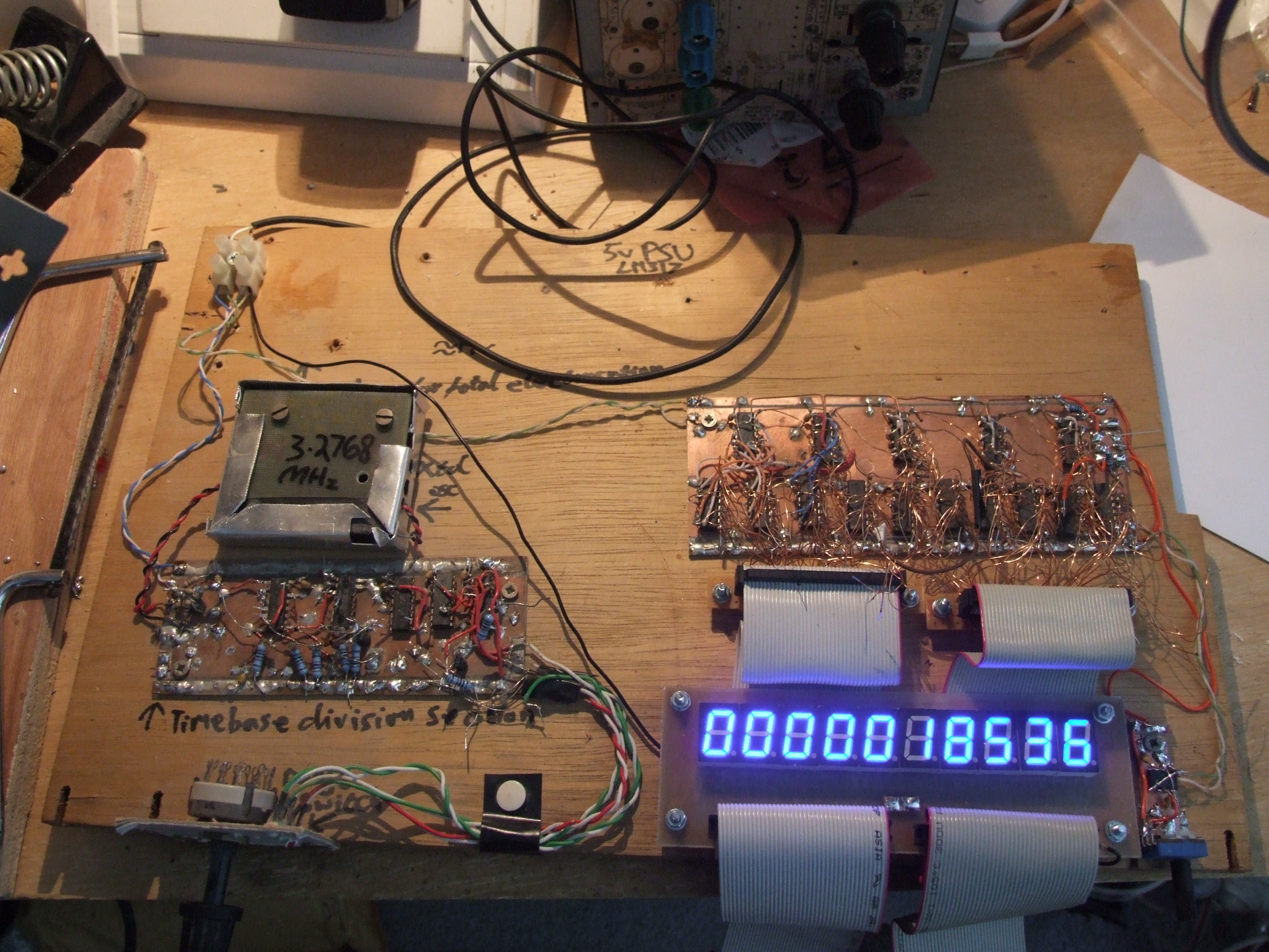
And then several hours to solder them all to the driver ICs, and correct the odd wiring mistake from when I first built this board. As you can see, it’s rather bright; in fact, so bright I quickly got a headache:
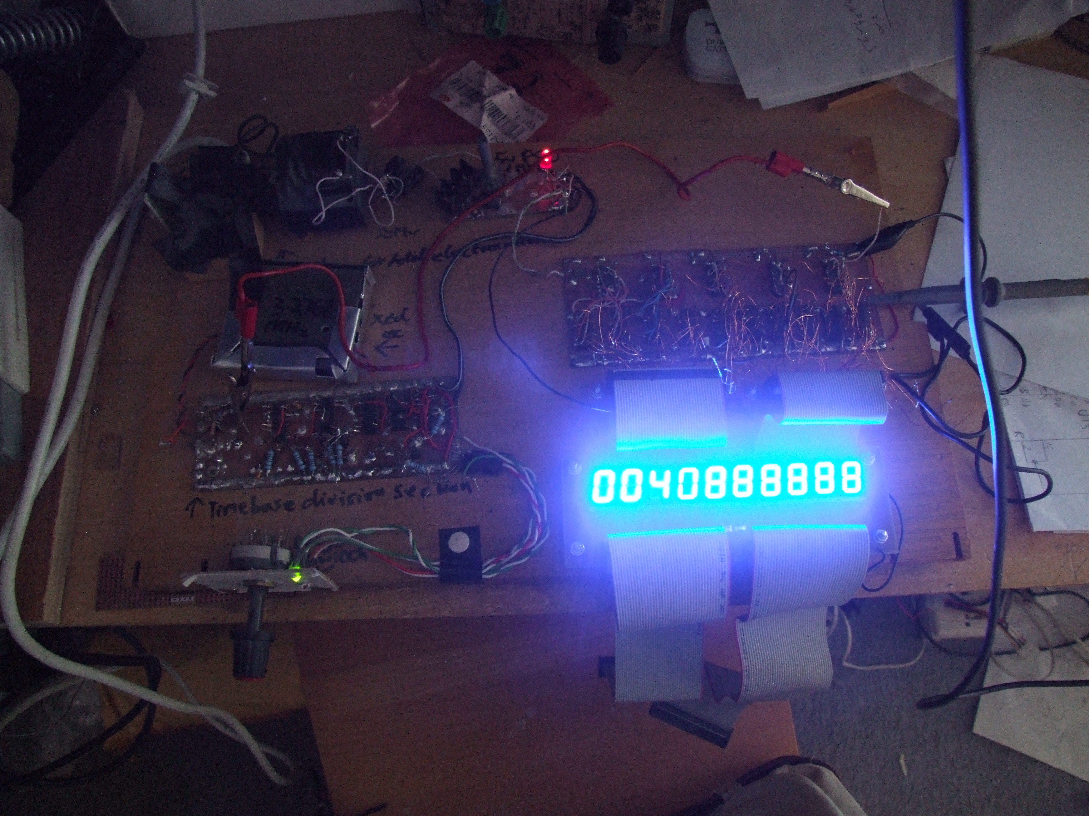
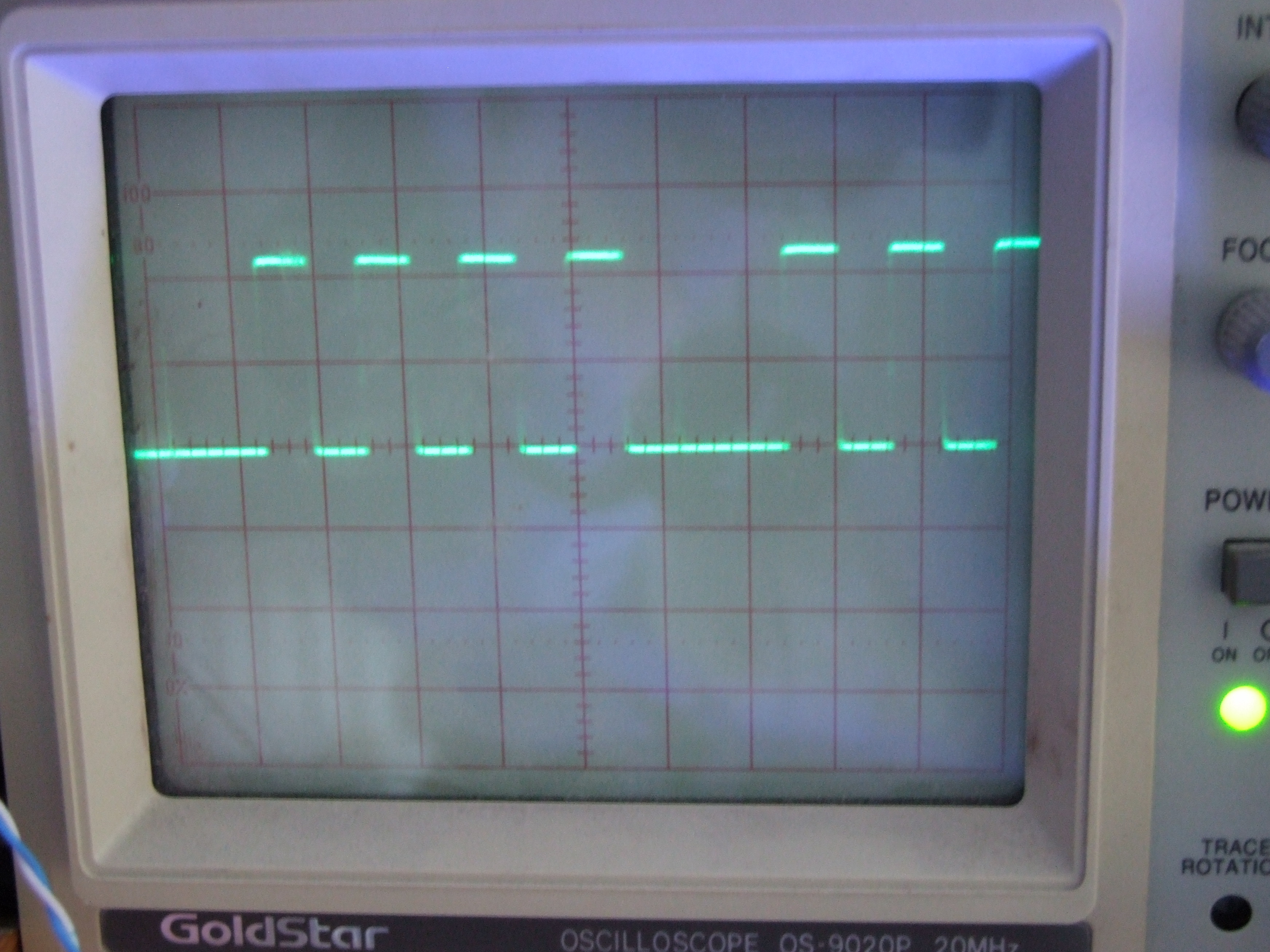
Those last digits are all ‘8s’ because they’re counting faster than persistence of vision, as the scope show:
The 74hc4051 driving the rightmost (LSB) digit didn’t work properly, probably because I had a bright idea and tried to strip some magnet wire attached to it and overheated it. I swapped it for an old 4511 (not HC) which was to cause me problems. For now it needed to be dimmer, and I wasn’t replacing those 150R resistors. PWM was the obvious way to go, and I threw together a test using the Pinguino and a transistor to switch the ground return. It does work:
…kind of: that 4511 is not driving properly. In fact, it doesn’t like working at all into a PWM load. I was stumped for a long time, and eventually decided to replace it and ignore the problem for now. So I build a 555 based PWM driver (the same one the whole internet builds) and connected it up. Then in a fit of inspiration I tried reading the datasheet for the 4511, which points out that the enable pin may be used for ‘brightness control’. Duh! Feeding the PWM into the enable and grounding the display board gives me a nice smooth adjustable brightness:
As you can see, there used to be a linear PSU on the board, but it was silly and inefficient so I replaced it with a 5v SMPSU of the plug-in kind. Now we have the counter and display: all that’s needed is the gating logic, an input amplifier and a case. I may, finally, finish this thing!