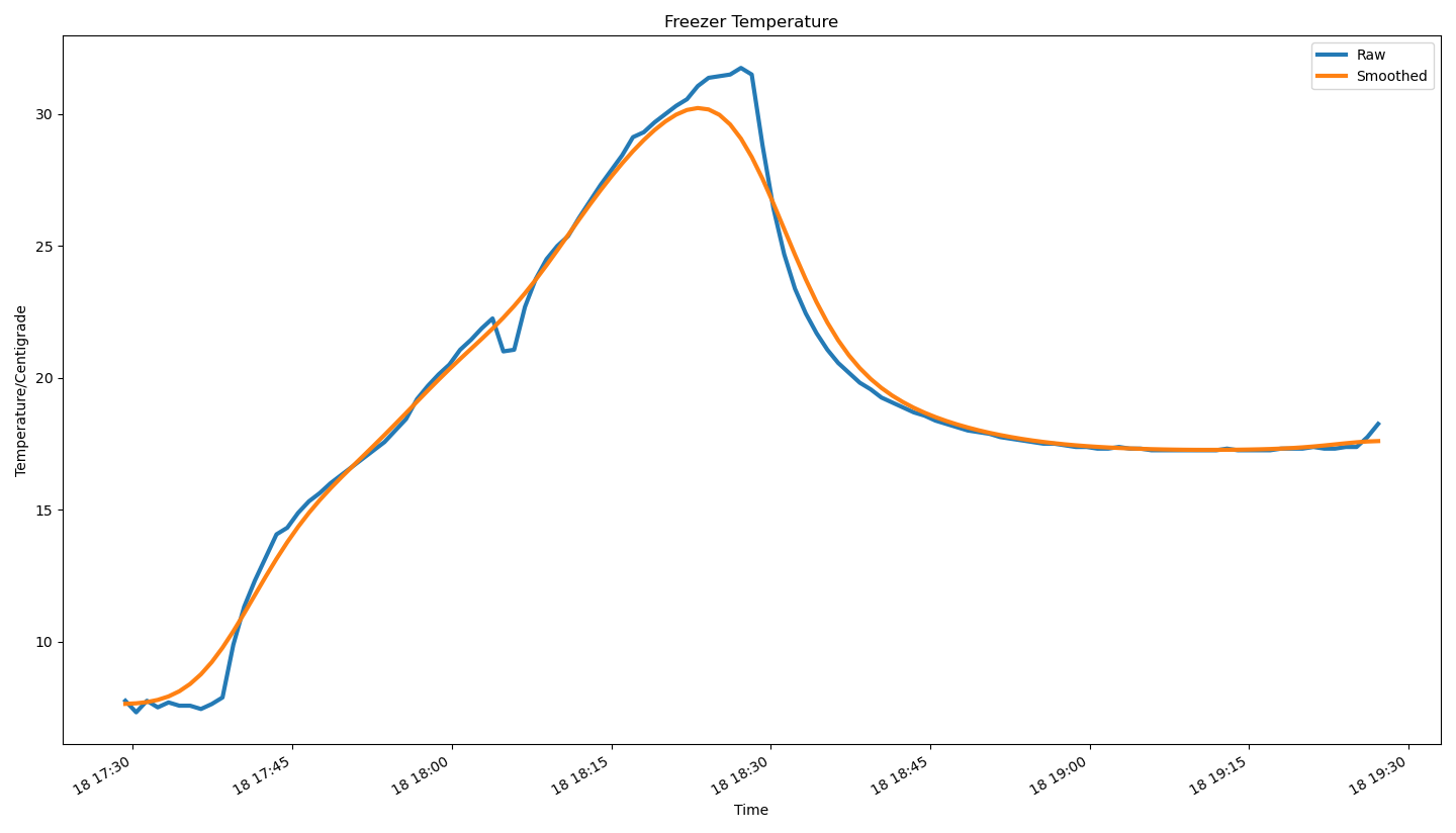
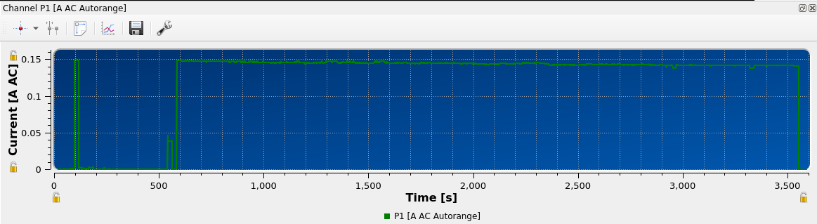
We have a Hotpoint FFA52 fridge-freezer. It has previously given much hardship. It no longer works. Here is a graph of a non-working freezer:
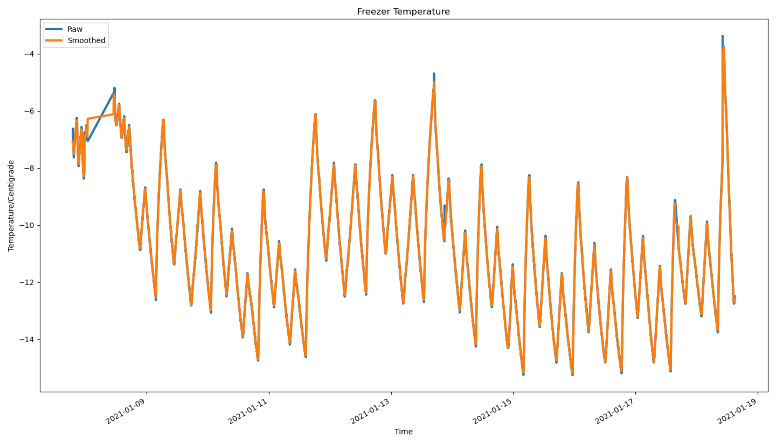
I don’t mind a bit of swing in the temperature, but that’s all over the place. In the meantime the fridge compartment turned into a freezer, albeit not a very good one. Time to take it apart and see what the problem could be.
Cooling System
This fridge-freezer has one fan, two thermistors (one in each compartment), one heat exchange (at the top of the freezer compartment), a duct around the heat exchange/fan which causes air to be drawn from the bottom of the freezer compartment and blown out at the top, recirculating via the door, a ‘superfreeze’ button which causes it get colder quicker (or possibly just colder) and is to be used ‘when the ambient temperature is below 16 degrees or you want to freeze fresh food’ and should be used ‘only for 24 hours, but always if the ambient temperature is below 16 degrees’, a light (in the fridge compartment), a door switch (in the fridge compartment), an uncalibrated knob to set the fridge temperature, and a power indicator, which never comes on. Attached to heat exchange is a defrosting coil and a thermal fuse, and another defrosting coil is in the polystyrene insulation directly below the heat exchange and in the duct.
For pictures of all this, see the previous post.
There is a control board at the very top of the freezer, in the same plastic membrane which supports the top door hinge. Every design decision here seems to be about cutting cost (why no third metal hinge?) and the plastic had become brittle, but despite snapping the clips taking it off the two screws seem to hold the door rigidly enough.
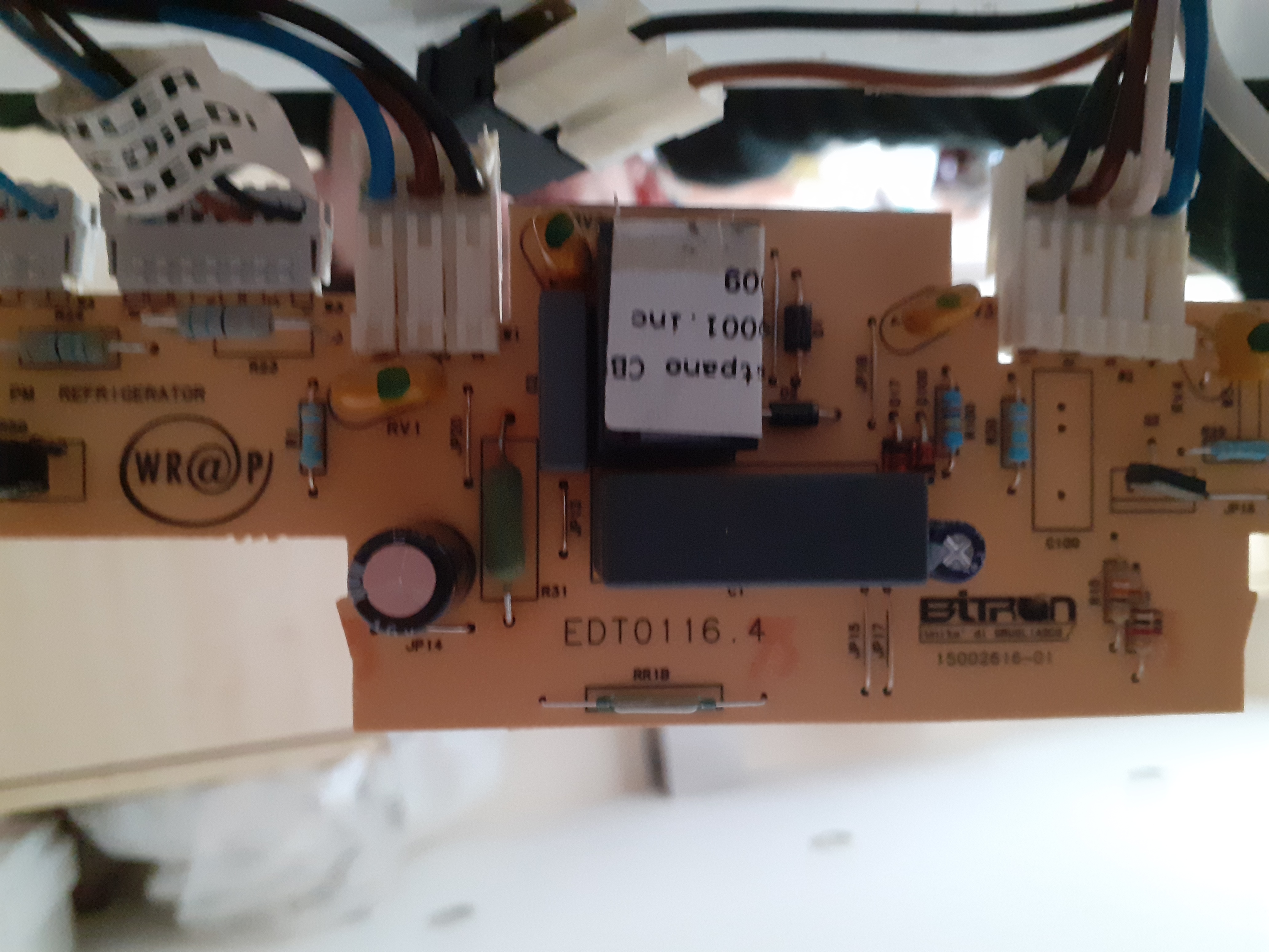
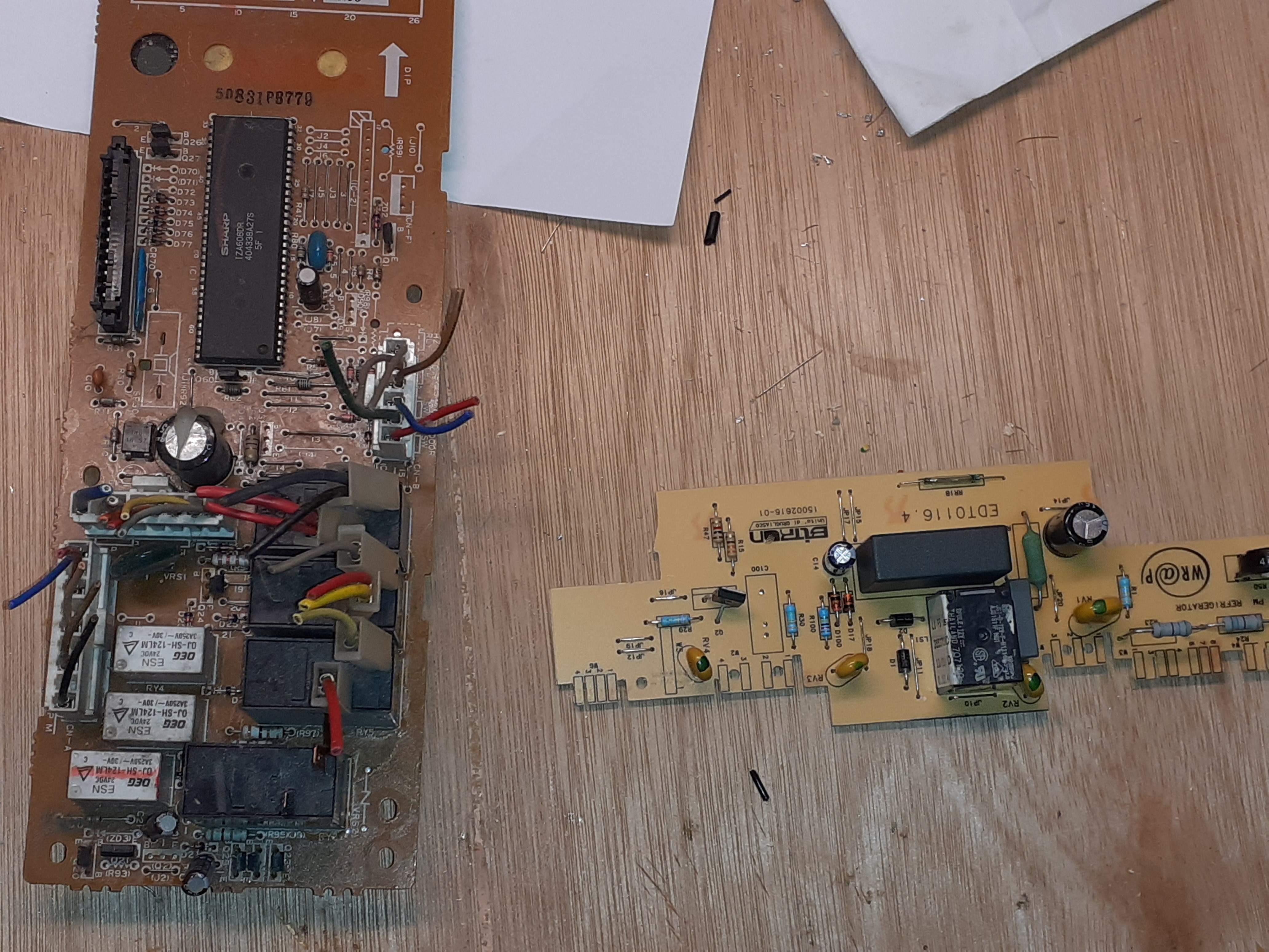
I removed the top membrane, cut notches in it where the two bundles of wires come out to meet the control board, removed (at the cost of a screwdrive gashing a fingertip) the control board from the membrane and reattached it with everything poked up on top. Now we can fiddle with the controller without having to take the fridge apart each time. Here is a poor photo of the control board:
and here is the other side, with the microcontroller:
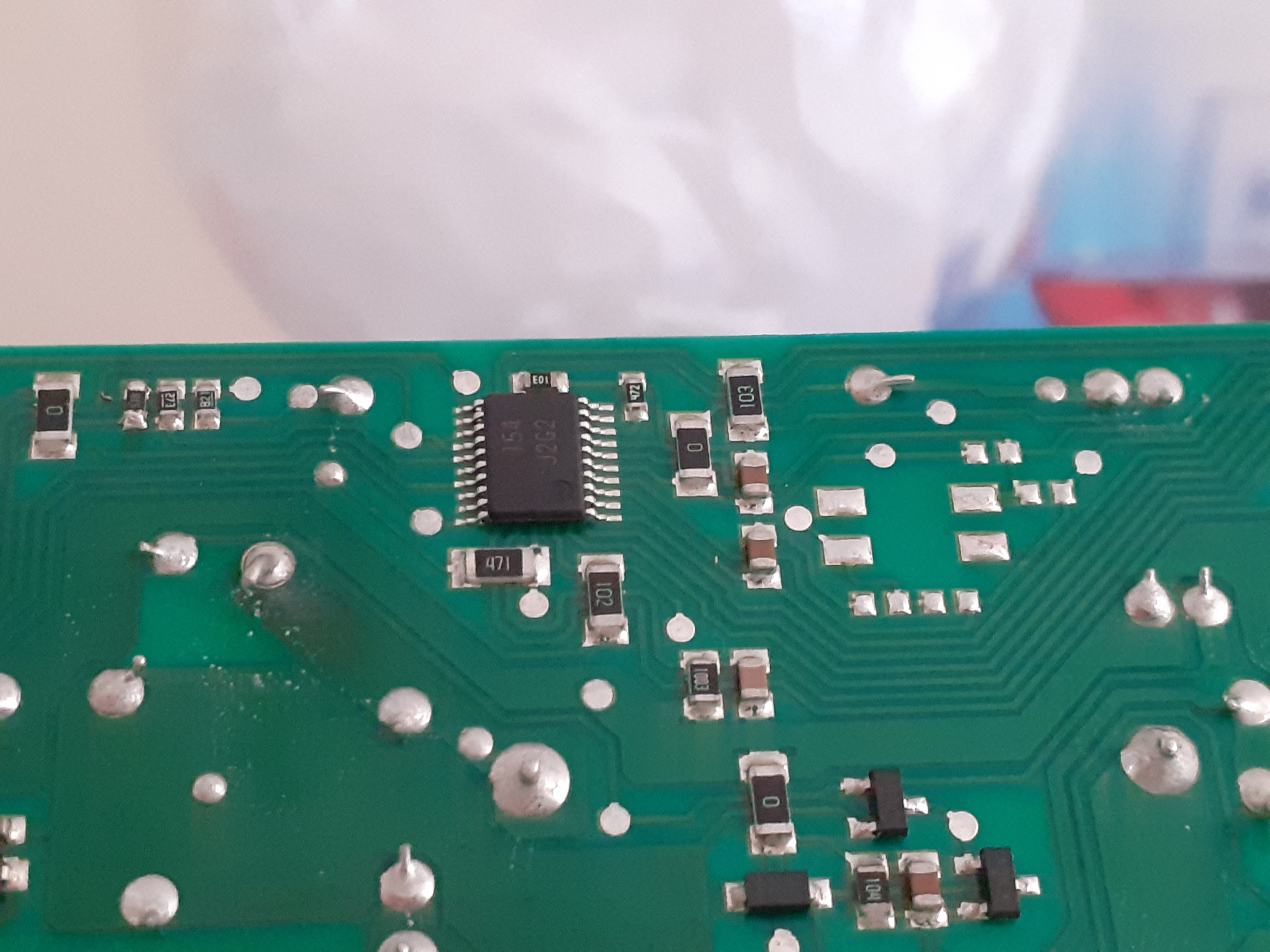
Alas, that’s a manufacturer-specific partnumber and I have no idea what this is, but probably an 8-bitter (or maybe it’s just a bunch of comparitors and not an MCU at all?). There goes the dream of hooking up an STLink and flashing new firmware. Still, it’s likely not the firmware (if there is any) which has gone.
We’re lucky enough to have another fridge and freezer, so I decamped everything and turned it off. Then I took the ducting off. It was frozen solid and took a hairdryer to move. Once off it was clear what had happened:
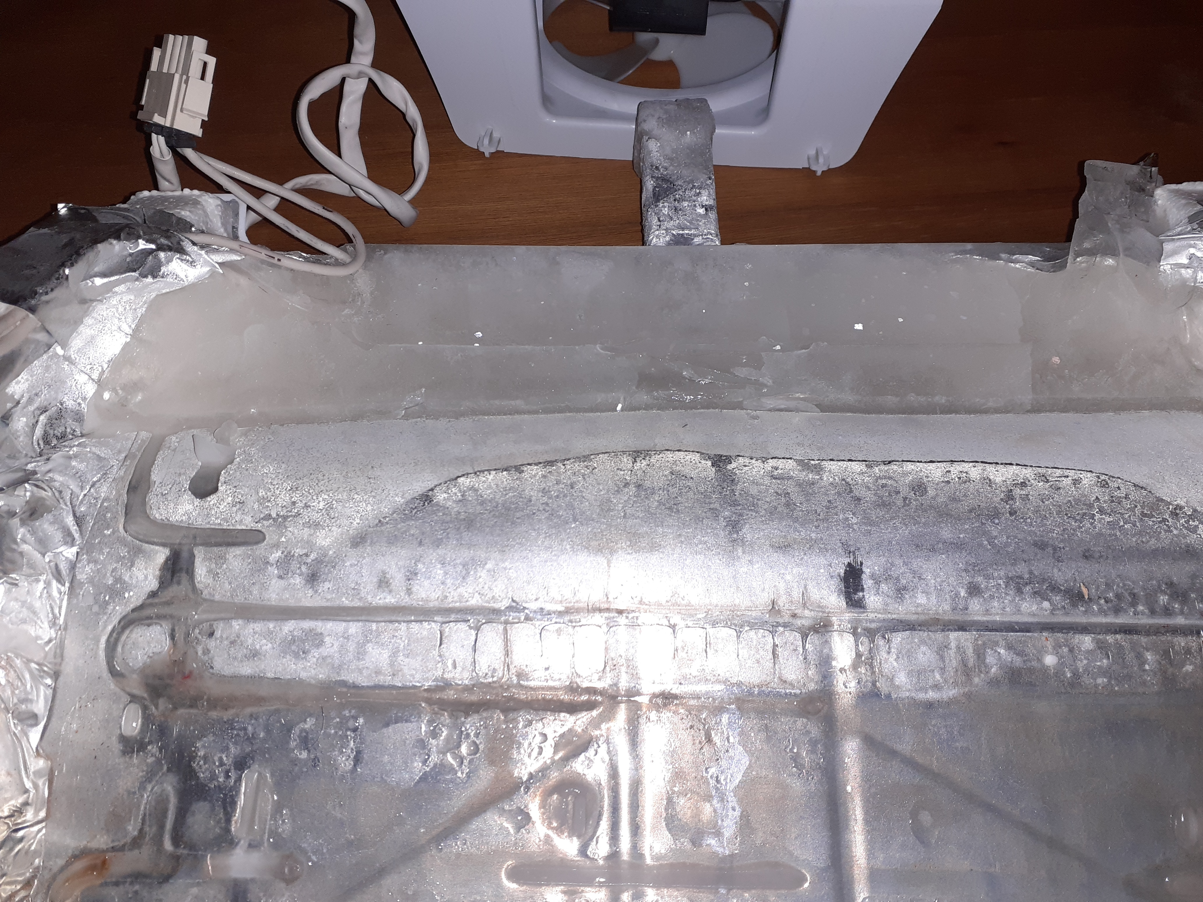
That’s ice, all along the back, right up to where it hit the inside of the compartment. No wonder it wouldn’t come. The overflow tube is a solid icycle. The heat exchange, crucially, looks fine however:
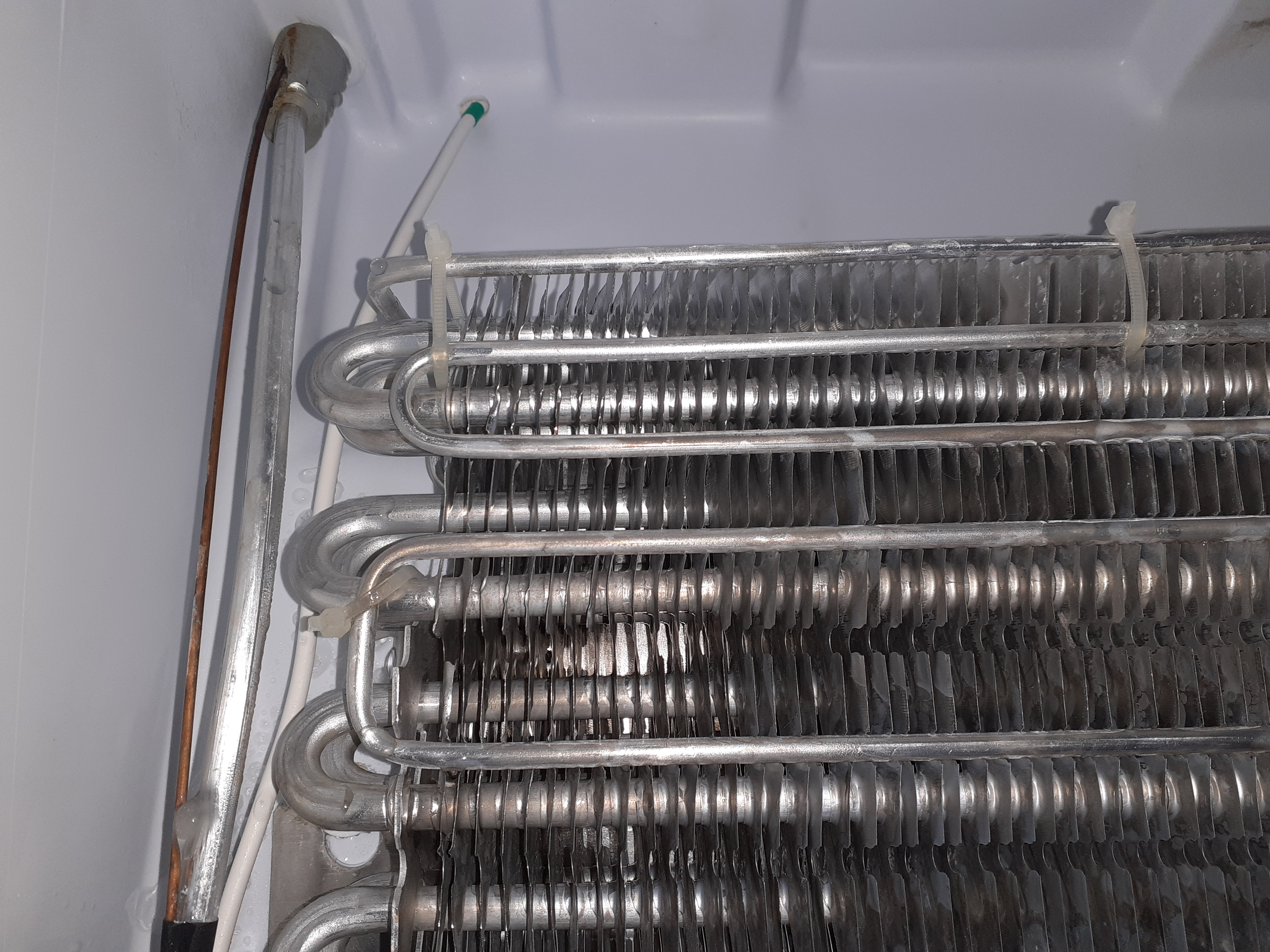
The coil in the foreground is the heater, the wire is to the thermistor and the the thermal fuse is on the other side.
Testing
What had gone wrong? My first guess was that either the fan had failed or one or both of the heating coils. The heat exchange wasn’t frozen solid and the heater attached to it measured only a few ohms, so it wasn’t that. The other heater was rather less inspiring at 6k, but 6k is not an open circuit and looked plausible. I thus took it upstairs, put it on a towel, and rigged up an experiment:
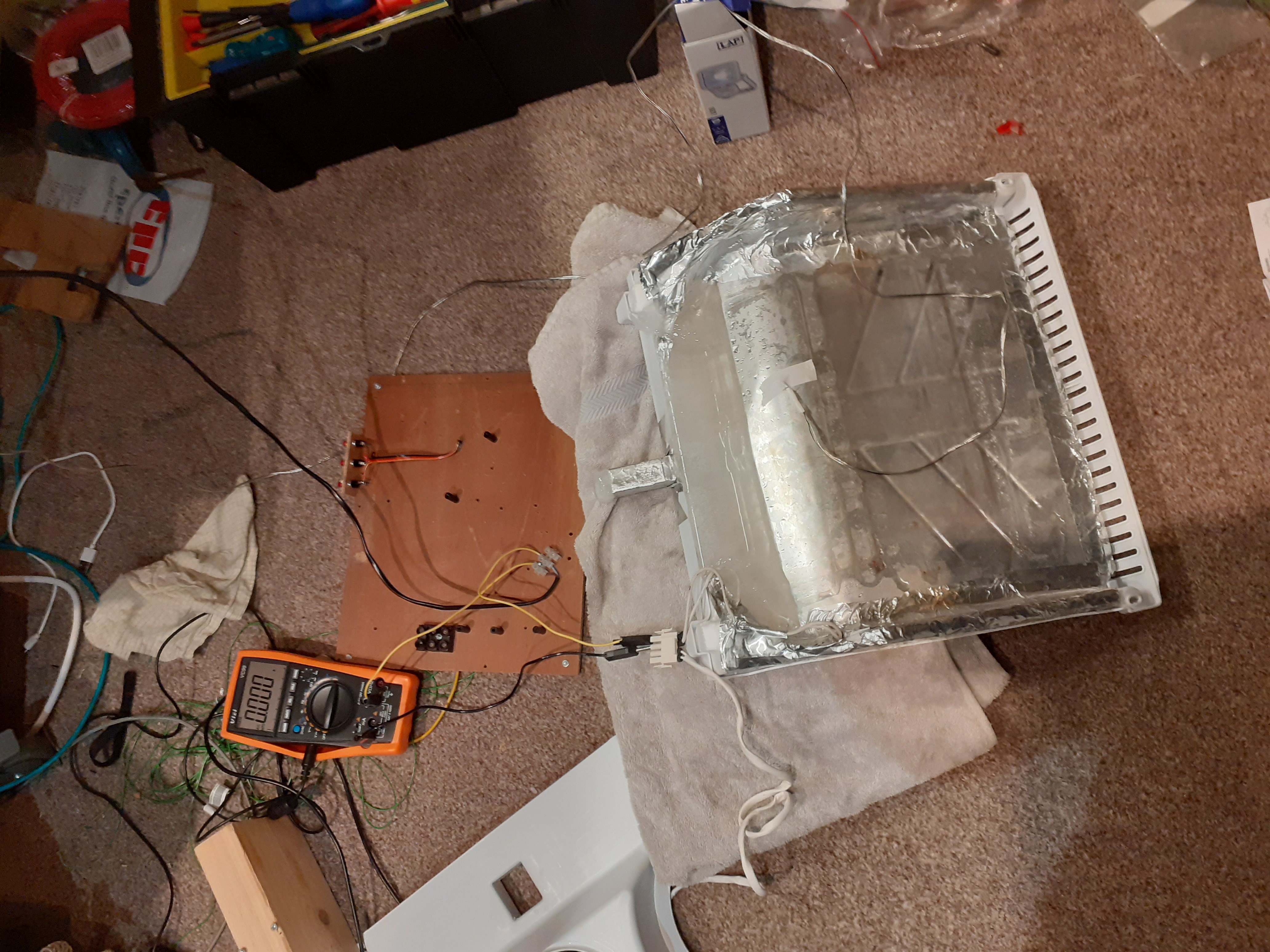
The multimeter is a Vichy VC99 with optoisolated serial output added to it, but multimeter hacking is for another post. Mains arrives by the black wire.
Well that clearly didn’t work, but I briefly saw 150mA being drawn. Perhaps it’s the connection? With some 2.5mm^2 wire bent and pushed in it started going:
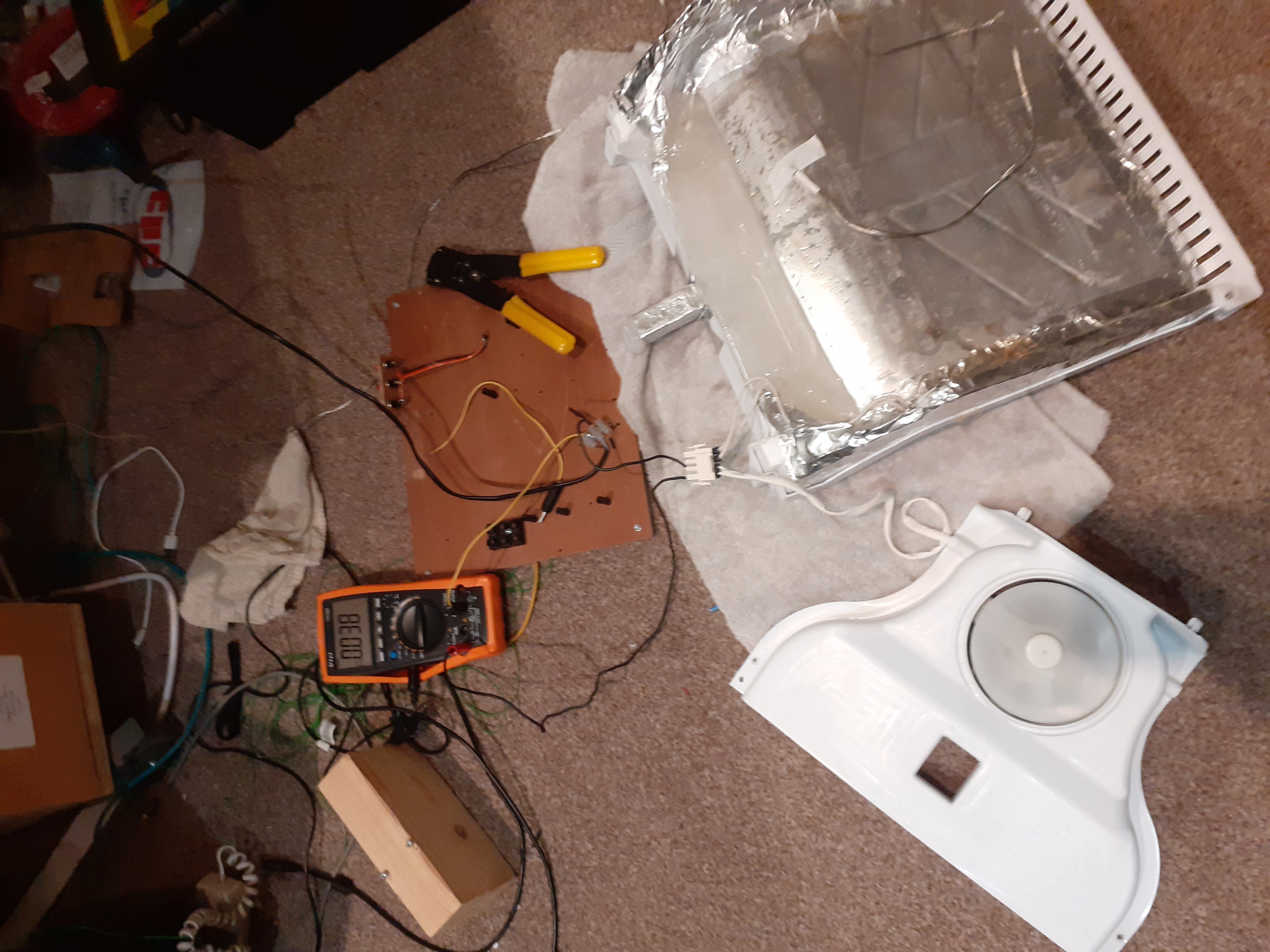
Which is actually a test of the fan, as you can see. The fan works; the heater works too:
Apologies for the screenshot. SmuView’s saving is currently broken and I haven’t had time to look at it.
Fan draws less than 50mA with a noticeable startup spike (probably higher as the multimeter only samples every 0.6s), heater draws 150mA.
So that can’t be it. Why, then, were they not getting switched on? I had another look at the controller board. It has a large 100nF capacitor, presumably as a capacitative power supply. It has a 12v relay, a lot of transistors, SCRs (or mosfets? But would have to be two/output if so, so unlikely), some high-power resistors (second power supply for the logic?) and handfull of passives, most notably varistors. What could go? The relay is for the compressor (highest current load). So the rest are on SCRs, which can go; or perhaps its a transistor somewhere?
As it happens, I’ve always wanted to build a fridge controller. So let’s just reverse-engineer the connections and start from scratch.
Reverse Engineering
Fridge Operation
There is no air-channel from the freezer to the fridge. So the usual blow-air-from-freezer block-channel approach can’t be in use. What else could it be? I was stumped for ages until I realised the insulation under the heat exchange is partly to insulate the freezer from the heat exchange. So the fridge is called by direct contact with the heat exchange + convection. Colder fridge = run compressor for longer. That explains why turning the fridge temperature to the lowest setting did cool the freezer, but froze the fridge.
Freezer Operation
How does the freezer cool, then? I was stumped a bit further, and wondered if they were doing something horrible like using a heater to stop it getting too cold (‘icebox in fridge’ fridges actually do this). Then I realised that the freezer will basically not cool if the fan doesn’t run, or if the airway is blocked. So run the fan = cool the freezer. The aggressive defrosting is to prevent exactly what has been happening.
How long do we defrost for? This will require some experimentation, but the presence of a thermal fuse suggests a reasonable time (unless it’s just a statutory requirement). The thermistor on the heat exchange should give us useful data on that.
Wiring
This was rather time-consuming and is specific to this fridge, but I eventually found I have two thermistors, one in each compartment, with a room-temperature resistance of around 20k and a negative temperature coefficient (tested with a hairdryer). Then there’s a connection for the lamp, power, connection to the heaters (which are in parallel, with a thermal fuse in series on each leg), the motor, the door switch, and separate switch for the ‘quick freeze’ option, which is wired directly to a tap on the compressor motor and probably just makes the compressor run faster. So to control everything we need to switch:
- the compressor (10A on their relay)
- the ‘go fast’ (10A to be safe)
- the light
- the fan
- the heaters
and recieve input from:
- the door (digital)
- the fridge thermistor (analogue)
- the freezer thermistor (analogue)
That’s 5 relays or SCRs (but I have no SCRs). Fortunately I have an old microwave controller with relays galore:
These are 24V relays, but 5*5 = 25, which is close enough, and a 5x voltage multiplier is easy enough. Switching current on the large relays is 50mA however, but with a soft-hold we can save current (so long as we don’t switch too many at once).
Time for part two: writing a fridge controller.