Like many ageing Honda Civics our VSA and ABS lights have been coming on sporadically for the last few months. Now they’re stuck on all the time.
First I suspected the battery, so I duly measured the no-load voltage (~12.6V: not great, but not awful either), the voltage dip when running the fuel pumps, (~11.6V) and the voltage dip when starting (briefly around 10V, but I didn’t have a scope on it). Yep, the battery is ageing. What about its internal resistance? Everyone did this at school, right—you put a load across the battery, measure the current through the load and the voltage across the terminals before and after; then you assume that voltage was dropped across the internal resistance and do R=V/I. The trouble is that the voltage drop is tiny, so you need a reasonable current. I couldn’t find any decent loads, but any load will do if you have an ammeter in series, so I disconnected the negative lead and used the car itself. Since the alarm promptly started going off (next time lock the car door!) that formed one data point, and then I turned the running lights on for the other. With the multimeter in relative mode even the subtraction was done for me:
| dV | I | R |
|---|---|---|
| 0.06V | 0.9A | 67mOhm |
| 0.3 | 6A | 50mOhm |
Neither is ideal, but both are perfectly respectable for a starting battery. Anyhow, it seems that measuring battery health this way is a pretty dark science—one paper I saw claimed that the usual means of measuring AC impedance and then taking the real component gave wildly different values from the DC resistance, so when I found the batteries had died (!) in my capacitor ESR meter I put it back. It’s not calibrated, so I would have had to find a bunch of 10ohm resistors to make up a 100mOhm calibration unit, anyhow.
Further confirmation that it’s not the battery came when trying with a charger across it, and a lithium ion jumpstarter which once rescued us on a motorbike on the side of the road. The warning lights refused to go away. There’s a procedure for resetting them without a code reader—ground the SDS pin on the odb connector or stuff some foil in the socket for the same purpose on the fusebox and play with the brake and the key. It clearly worked, but the light came straight back again.
Thus I turned to the sensors themselves.
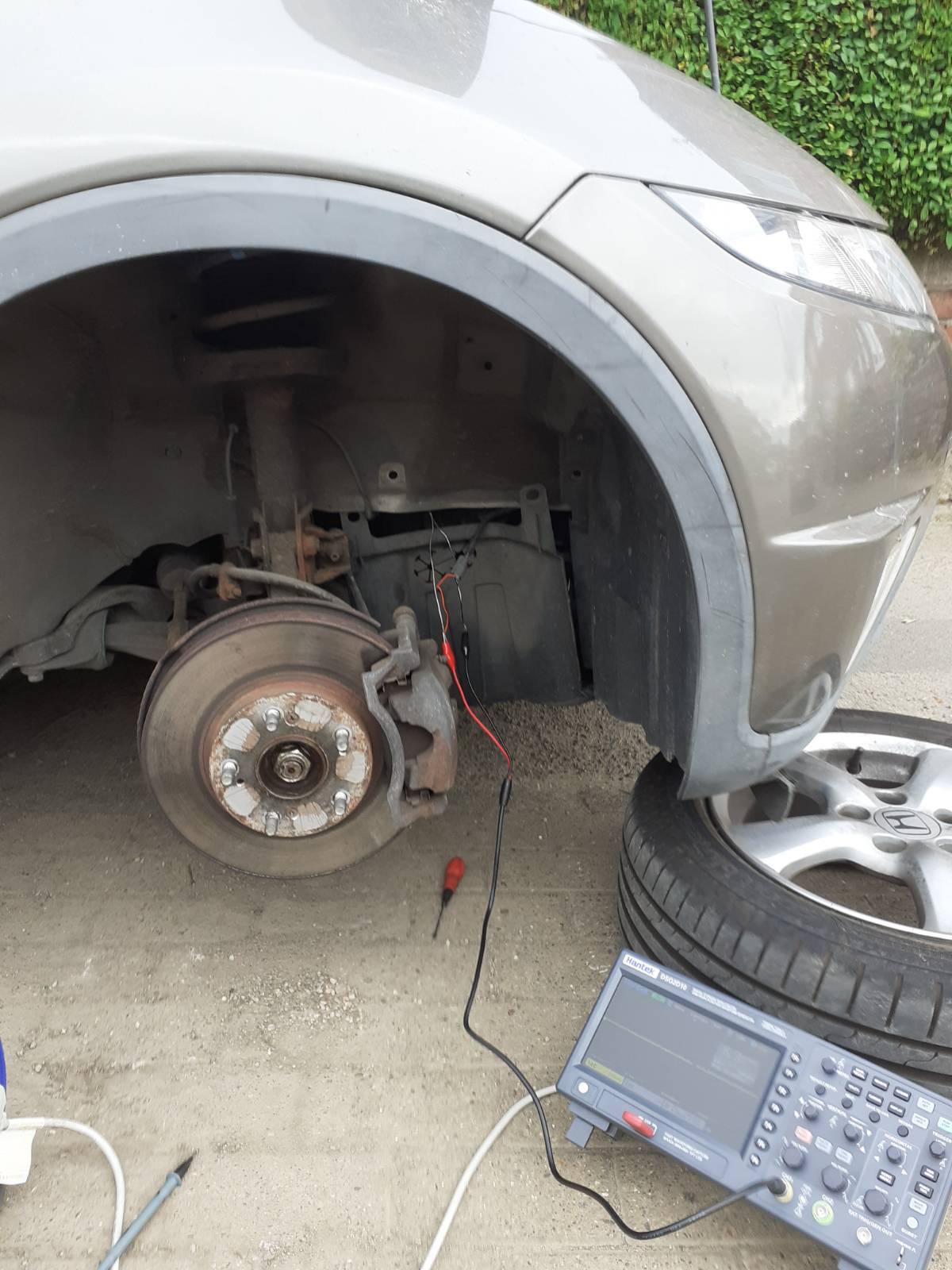
All the wheels are different, to be annoying, and I had to work one wheel at a time as the pavement grounds my low profile jack on one side. I also jacked from the pinch welds for the first time and promptly bent them flat, but never mind, they’ll work just as well like that. I mostly use them for axle stands anyway.
With some wires and a lot of annoying poking around I managed to get connections to both the hidden pins and the hidden sockets. Front right worked perfectly:
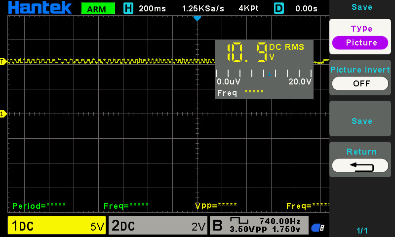
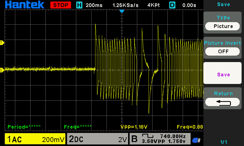
My notes claim the sensor measured 1.5 M Ohms, but on the basis that the other three working sensors were in the 280-300k range I wonder if I didn’t misread. Here you can see the search protocol from the abs controller:
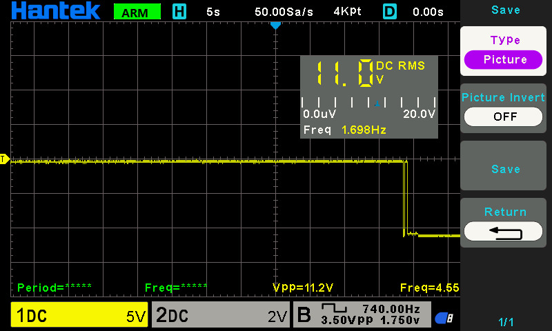
(Apologies for the trace being upside down.) There are two 11V peaks, which clearly are used to measure drawn current, and then if the sensor is detected the line is held high at 11v and the wheel movements are modulated on to it. The rear right sensor had the two peaks (so the wiring’s good) but nothing I could do could make it stay high after that. The sensor also measures 2 M Ohms (hence the comment about misreading the front right).
Thus a new sensor is in the post for £10, and we’ll have to see if it can be fitted easily. These sensors are very simple—hall effect probes—so hopefully the inside of the drum isn’t full of rust or something preventing it working. The outside of the brake and the whole rear of the car certainly shows its age.
And digital oscilloscopes are really good fun—this would have been a nightmare with the old crt scope. Now I just need to learn how to take screenshots without the screenshot bar on the right hand side…